Installation and Set-up
2-5
S5 UniLink Adapter Installation and Operation
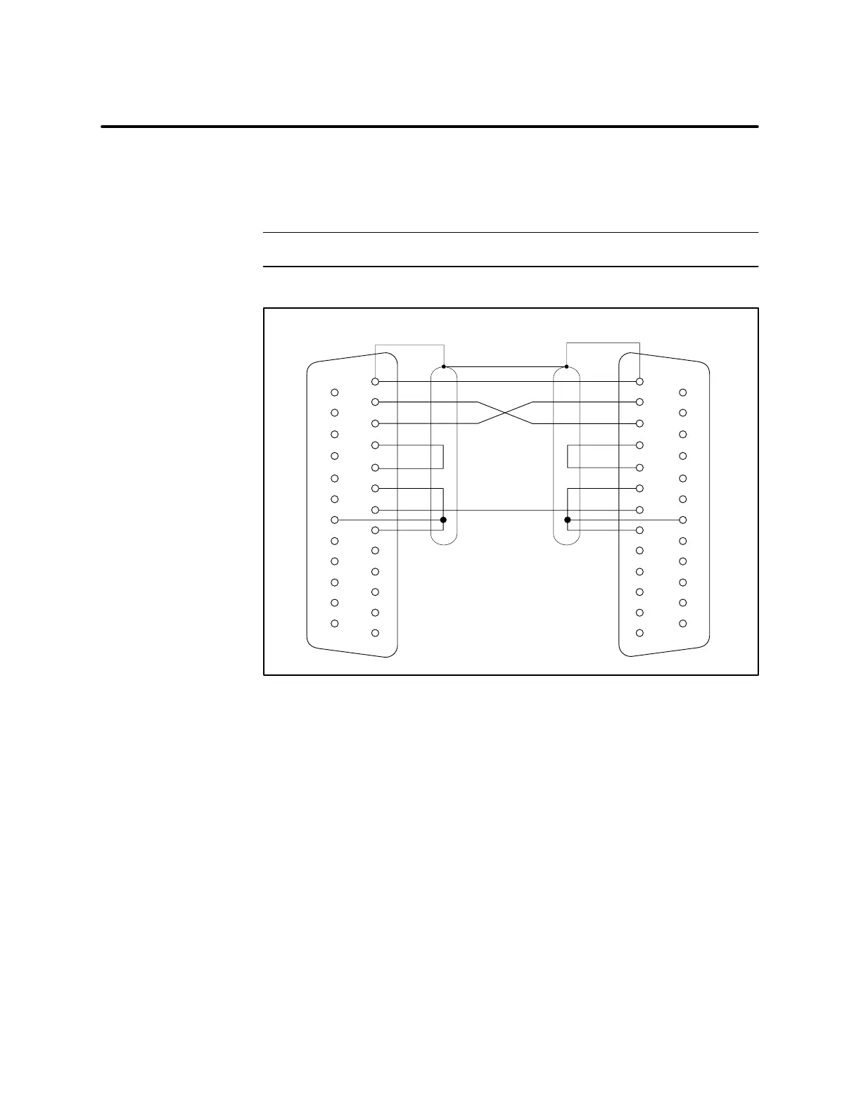
The pin assignments for the S5 interface are shown in Figure 2-3. Any pins
not listed in the diagram should remain unused in order to prevent damage
to the communications processor or the S5 UniLink Adapter.
NOTE: Do not exceed 50 feet in length for the communications cable.
1
2
3
4
5
6
20
8
7
1
2
3
4
5
6
20
8
7
(DTE) (DTE)
GND
99
10 10
11 11
12 12
13 13
CP 525 Communications Processor S5 UniLink Adapter
14
14
TD TD
RD RD
RTS RTS
CTS CTS
GND
DSR
DCD
DSR
DCD
25
25
DTR DTR
I003642
Figure 2-3 Pin Assignments for Connecting S5 Adapter to CP 525
S5 Interface Pin
Assignments

 Loading...


