Installation and Set-up
2-6
S5 UniLink Adapter Installation and Operation
2.3 Setting the Dipswitches
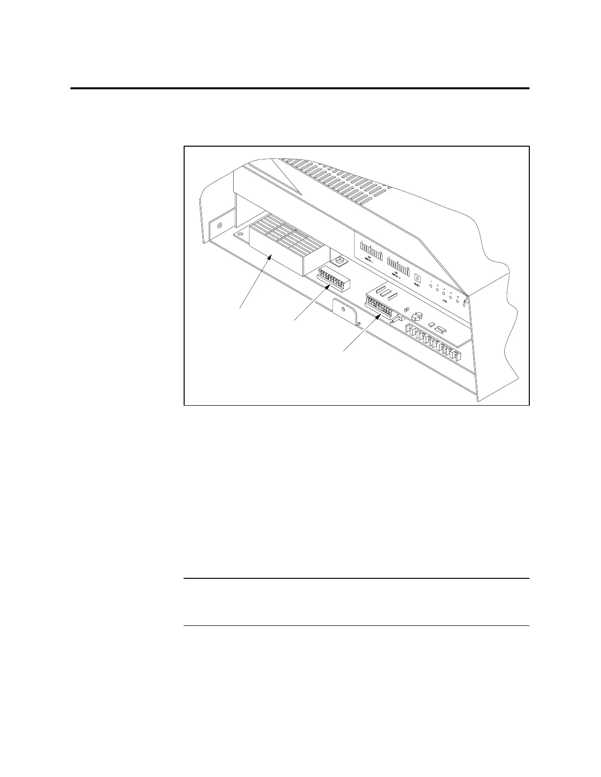
Two banks of dipswitches are provided on the S5 UniLink CPU board,
accessible by opening the cover plate on the face of the unit (see Figure 2-4).
A000653a
S5 PIM
Dipswitch 1
Dipswitch 2
I003643
Figure 2-4 S5 UniLink Adapter Dipswitch Location
Dipswitch 1 is used to configure the S5 Interface Port and the TIWAY
network port, as shown in Figure 2-5.
The data rate of the S5 UniLink Adapter interface port can be set for either
9600 or 19,200 baud using switch 3 on Dipswitch 1 (see Figure 2-5). The
remaining communications parameters are fixed as follows: 8 data bits,
even parity, and 1 stop bit. Be sure to program the attached CP 525 module
to accept the S5 UniLink Adapter’s communication parameters.
NOTE: Set switches 1 and 2 to correspond to the CPU number with which
you want the S5 UniLink Adapter to communicate. Refer to the CP 525
manuals for more information about the CPU number.
Dipswitch 2 is used primarily to configure the secondary address of the
S5 UniLink Adapter (see Figure 2-6). Refer to your UNILINK Adapter
Installation and Operation Manual for dipswitch settings.
Dipswitch Location
Dipswitch 1
Dipswitch 2

 Loading...


