TIWAY I Network Communication
3-5
S5 UniLink Adapter Installation and Operation
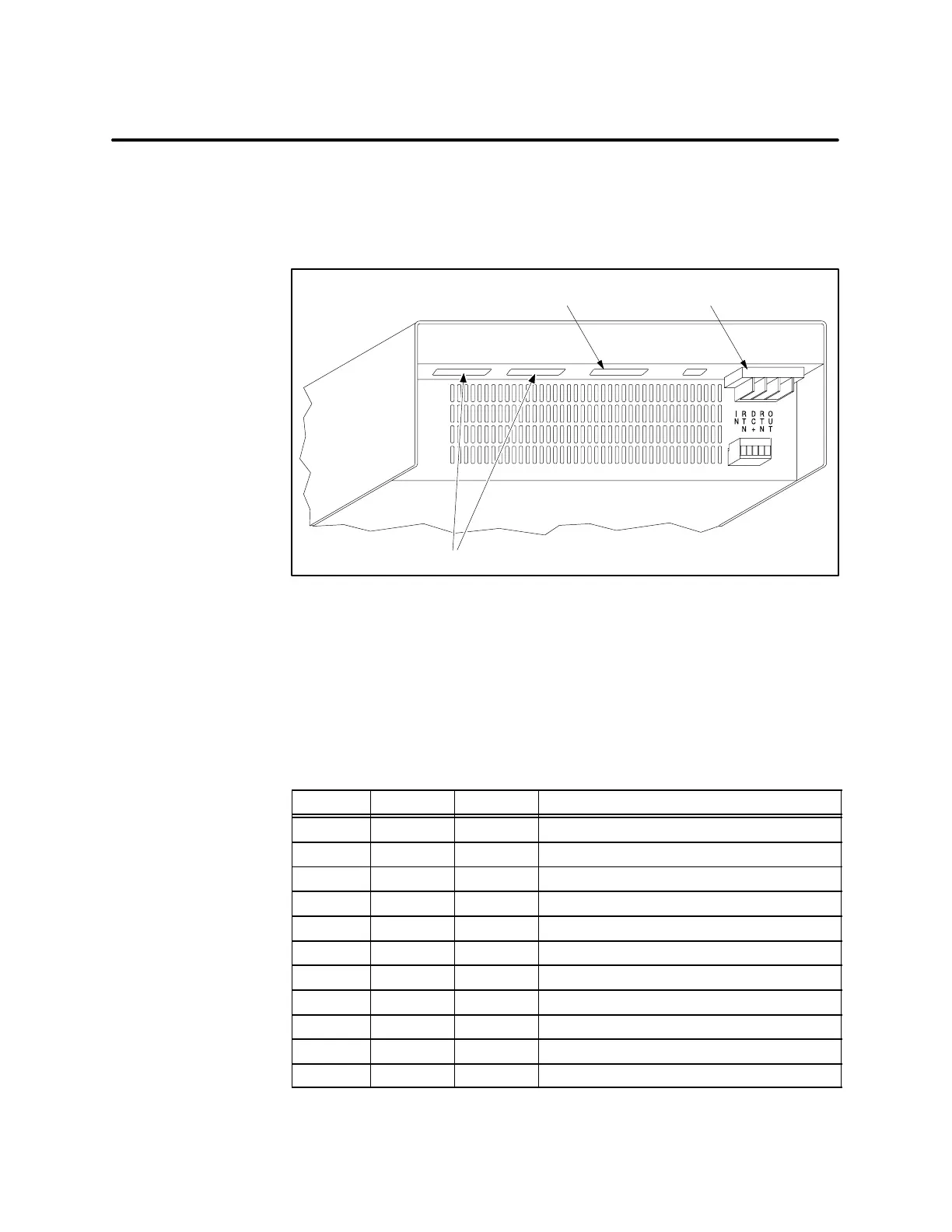
3.2 Modem Interface Ports
The modem interface is a standard Type E DTE configuration as defined in
the EIA RS-232-C standard that uses EIA RS-423 drivers. This interface
uses a female 25-pin D-type connector on both Ports 1 and 2 as shown in
Figure 3-4.
A000654
Port
1
Port
2
Port
3
Port
4
AC
NEUT
AC
LINE
GND
1 2 3 4 5
I/O
RS-232 S5 Interface Port Power Connections
Dual RS-232 modem interface ports
Figure 3-4 RS-232/RS-423 Modem Interface Ports
These two ports support redundant media transmission when connected to
redundant modem networks. The pin assignments shown in Table 3-3 are
supported. All other pins should be left vacant to prevent damage which
may be caused by nonstandard pin usage.
Table 3-3 RS-232/RS-423 D Connector Pin Assignments
Pin No. CCITT Circuit Description
1 101 AA Protective Ground
7 102 AB Signal Ground
2 103 BA Transmit Data
3 104 BB Receive Data
4 105 CA Request to Send (RTS)
5 106 CB Clear to Send (CTS)
6 107 CC Data Set Ready (DSR)
20 108/2 CD Data Terminal Ready (DTR)
8 109 CF Data Carrier Detect (DCD)
15 114 DB Transmitter Signal Element Timing
17 115 DD Receiver Signal Element Timing
RS-232-C Modem
Interface Ports
Modem Port
Pin Assignments

 Loading...


