4
4.2 Process data (PZD area)
4-119
E Siemens AG 2013 All Rights Reserved
SIMODRIVE POSMO A User Manual (POS1) – 08/2013 Edition
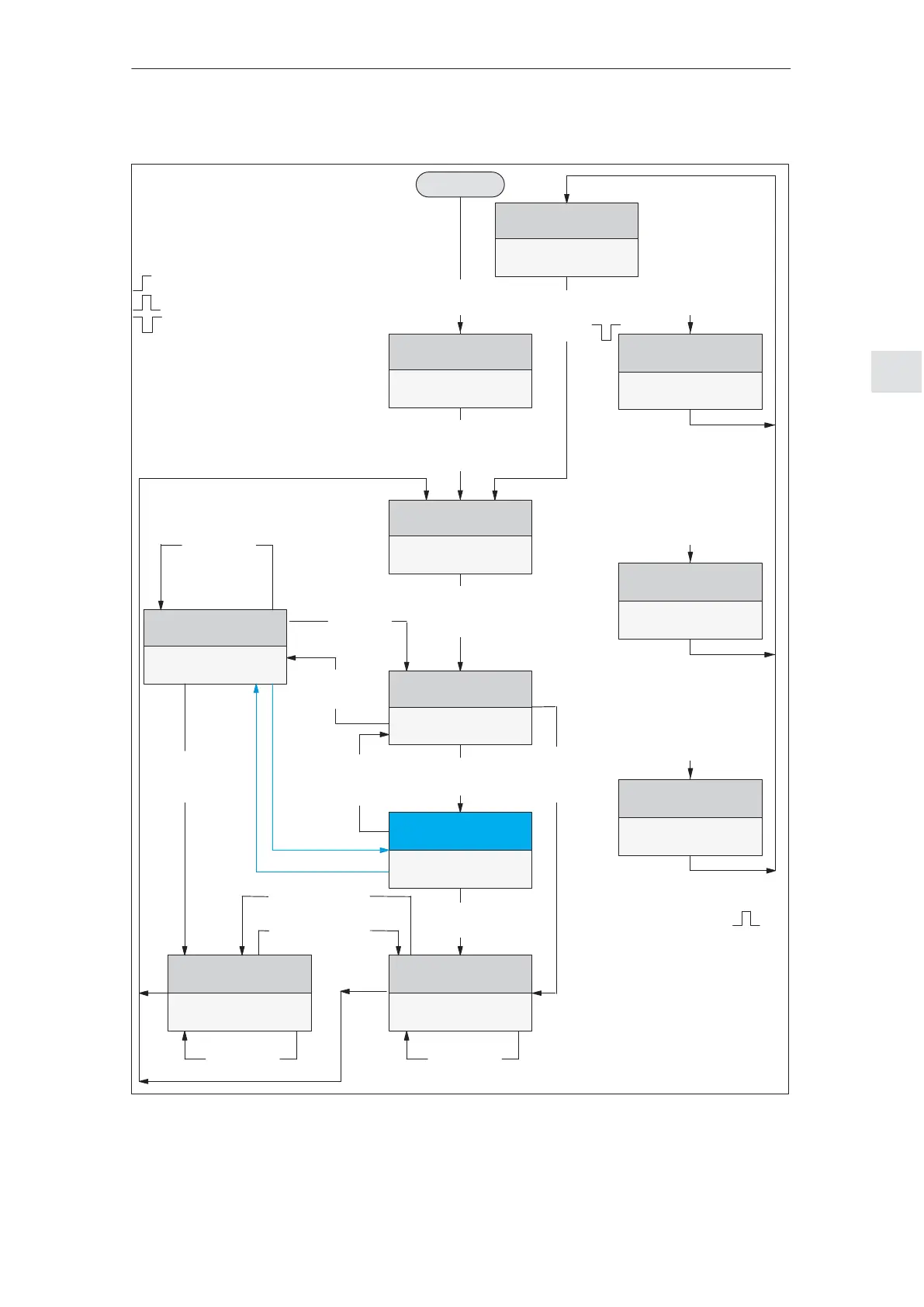
STW.6 = 1
1)
STW.6 = 0
1)
Setpoint
inhibit
i.e. STW.6 = 0
Enable
setpoint
i.e. STW.6 = 1
Fault
ZSW =
xxxx xxxx xxxx 1xxx
Fault
(from any
device status)
Fault resolved,
acknowledge faults
i.e. STW.7 =
OFF 3 active
ZSW =
xxxx xxxx x10x x000
No OFF 3
i.e. STW.2 = 1
OFF 3
i.e. STW.2 = 0
(from any
device status)
OFF 2 active
ZSW =
xxxx xxxx x1x0 x000
OFF 2
i.e. STW.1 = 0
(from each
device status)
Power–on inhibit
ZSW
x00x x111 x111 0000
Speed setpoint is accepted
i.e. STW.4/5/6 = 1 (any
sequence)
Initializing
i.e.
STW = xxxx xxxx x000 1111
Operation enabled
ZSW =
1x0x xxxx x000 1111
Braking down to zero
speed along a ramp
ZSW =
xxxx xxxx x0x1 1111
Voltage
ON
Speed actual value is
kept constant
ZSW =
xxxx xxxx x101 1111
Ramp–up to the
setpoint
ZSW =
xxxx xxxx x111 1111
STW Control word
ZSW Status word
p Bit dep. on the program (0 or 1)
s Traversing task bit of the STW
x Bit not defined (0 or 1)
Change from 0 to 1 or 1 to 0
Change from 0 to 1 and back again
Change from 1 to 0 and back again
1) this is only valid if STW.5 = 0
(the speed actual value is kept
constant)
START
No OFF 2
i.e. STW.1 = 1
Braking with maximum
acceleration
ZSW =
xxxx xxxx x1x0 1111
Braking with maximum
acceleration
ZSW =
xxxx xxxx x0x0 1111
Braking
i.e.
STW.4 = 0
Speed
constant,
i.e. STW.5 = 0
Speed
constant,
i.e. STW.5 = 0
Braking
i.e. STW.4 =0
Inhibit setpoint
i.e. STW.6 = 0
Setpoint enable
i.e. STW.6 = 1
Speed
constant,
i.e. STW.5 = 0
Braking
i.e.
STW.4 = 0
OFF 1
i.e.
STW.0 =
Not ready to
power–up
ZSW =
x00x x111 x000 x000
Constant speed,
i.e. STW.5 = 0
Speed
increases,
i.e. STW.5 = 1
Fig. 4-6 Flow diagram ”Variable–speed drives” for the n–set mode
n–set operation
4 Communications via PROFIBUS–DP
02.9905.03