5
5.5 SIMODRIVE POSMO A functions
5-194
Siemens AG 2013 All Rights Reserved
SIMODRIVE POSMO A User Manual (POS1) – 08/2013 Edition
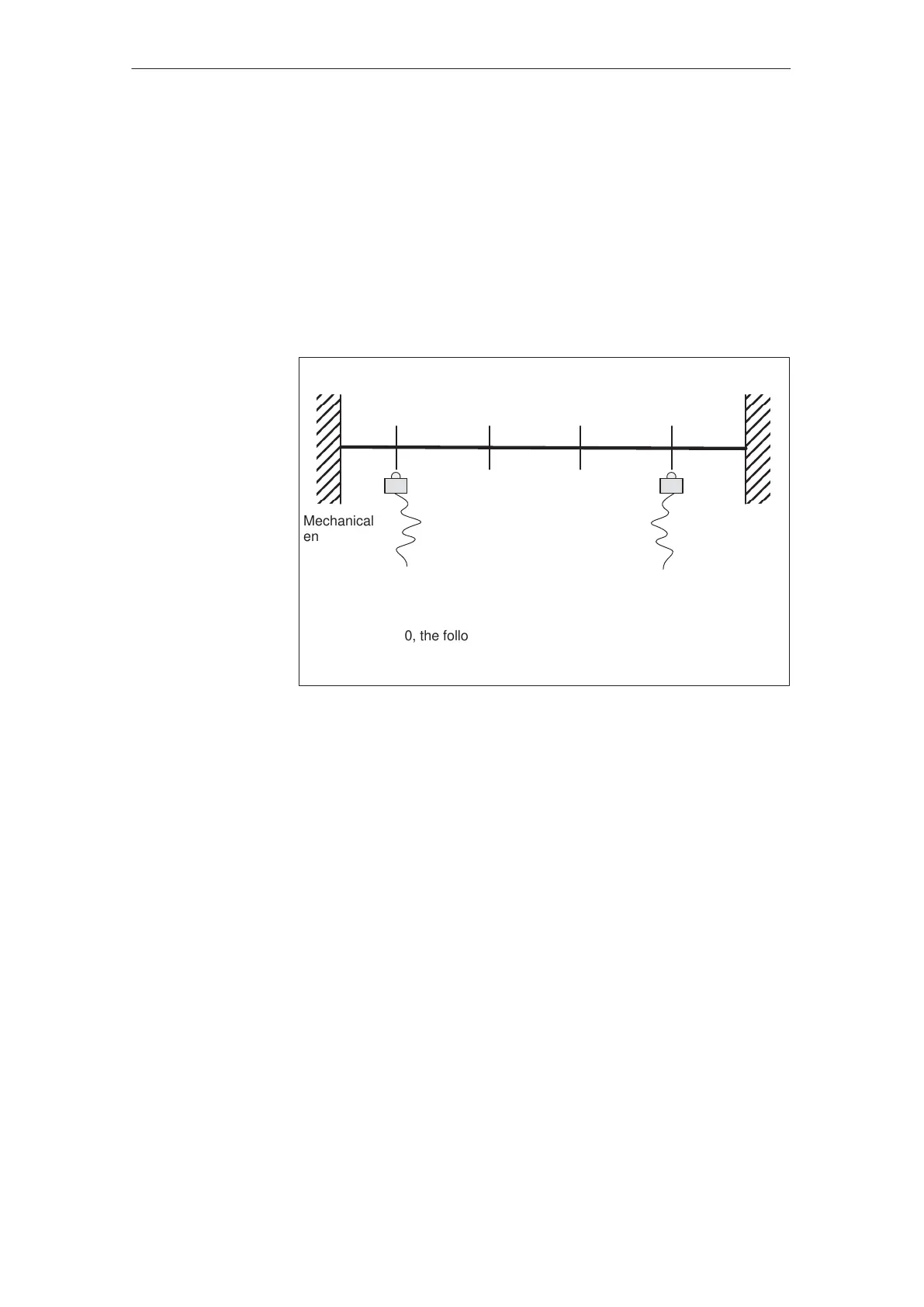
5.5.14 Limit switch monitoring functions
For POSMO A, the following limit switch monitoring functions can be
used:
Hardware limit switch (from SW 2.0)
Software limit switch
The limit switch monitoring functions can be used to limit the operating
range or to protect the machine and are also available in the n–set
mode.
Mechanical
end of
traversing
range
Mechanical
end of
traversing
range
Hardware limit
switches start
(normally open
contact)
1)
Hardware limit
switches end
(normally open
contact)
1)
Software limit
switch start
P6
Software limit
switch end
P7
Input terminal
with function number 28/30
1)
”hardware limit switch, start”
Input terminal
with function number 29/31
1)
”hardware limit switch, end”
1) From SW 3.0, the following applies:
The hardware limit switch can also be implemented as NC contact
(refer to P31/P32).
Fig. 5-21 Limit switch monitoring functions
There is a hardware limit switch for every axis and every approach di-
rection. The hardware limit switches must be connected to an input ter-
minal (P31/P32) with the following function numbers.
Function ”hardware limit switch start” ––> function number 28
Function ”hardware limit switch, end” ––> function number 29
––> Refer to Chapter 5.6.2
When traversing to a hardware limit switch, the associated input signal
is set and the following response is automatically initiated:
The axis is braked down to the maximum velocity set using P28
(maximum velocity).
The following fault is signaled:
– Fault 706/707 software limit switch, start/end
– Supplementary info 911 hardware limit switch, passed/reached
Description
Hardware limit
switches
(HW limit switch)
Traverse to a
hardware limit
switch?
5 Description of the Functions
02.9908.0406.05