2
2.3 Connection and wiring overview
2-45
E Siemens AG 2013 All Rights Reserved
SIMODRIVE POSMO A User Manual (POS1) – 08/2013 Edition
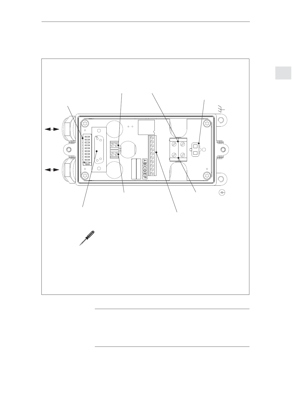
X1
Load power
supply
Input/output
X6 /X9
Internal load power supply
Note:
Equipping differs depending on
whether it is a 75 W or 300 W motor
X5
3L+ +24 V electronics supply
input (optional)
3M 0 V ground
1VS Supply 1
I/Q1 Digital input/output 1
1M 0 V ground
2VS Supply 2
I/Q2 Digital input/output 2
2M 0 V ground
4L+ +24 V electronics power supply
output (optional)
4M 0 V ground
X4
PROFIBUS–DP cable
Input/output
S1
Setting
S PROFIBUS
Node address
(station address)
S PROFIBUS
Terminating resistor
X7
Internal interface
X2
Load power supply
Input/output
X3
PROFIBUS–DP
cable
Input/output
Note:
Screwdriver for terminals (slotted screws)
Where? Size! Tightening torque!
S X1 and X2 1 (0.5 x 3.5) 0.6...0.8 Nm
S X3, X4 and X5 0 (0.4 x 2.5) 0.22...0.25 Nm
1VS
I/Q1
1M
2VS
I/Q2
2M
3M
3L+
4L+
4M
L1
X6
X2
5M
5L+
6L+
6M
X5
B1 A1
B2 A2
X3
X4
S1
X7
X1
X9
Fig. 2-15 SIMODRIVE POSMO A connection cover from the bottom
Caution
The screws are not screwed tight into the terminals when the system is
delivered. These must be tightened with the specified tightening
torque, in particular for unused connections as well, otherwise the
screws may fall out under heavy vibration.
Connection cover
from the bottom
2 Installing and Connecting–Up
02.9908.04