2
2.3 Connection and wiring overview
2-46
E Siemens AG 2013 All Rights Reserved
SIMODRIVE POSMO A User Manual (POS1) – 08/2013 Edition
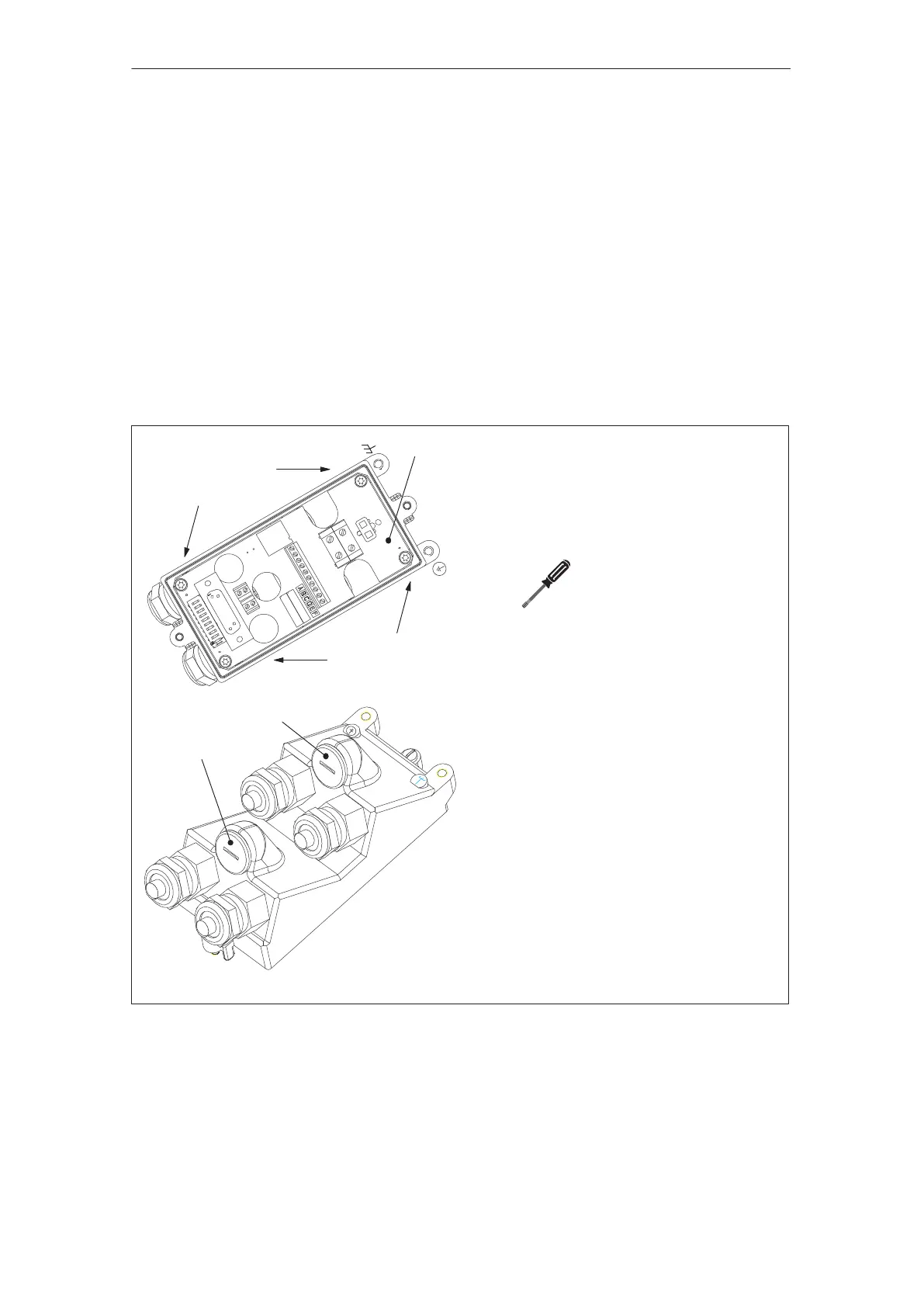
The cable outlet direction is, as standard, in the opposite direction to
the motor drive shaft.
Depending on the mounting situation, the cable outlet direction of the
positioning motor can be changed.
How can the cable outlet direction be changed?
––> refer to Fig. 2-16
1. In the unwired connection cover, release the four screws of the con-
nection module.
2. Rotate the connection module and screw back into place.
3. Interchange the load current and PROFIBUS cabling in the connec-
tion cover at the top.
Screw type: Cheese–head screw
M3 x 6 – 8.8
SN 60730
Connection cover
from the bottom
Connection cover
from the top
Screws
Screws
Connection module
Dummy plug 1
Dummy plug 2
After turning the connection module,
connect–up as follows:
S Dummy plug 1
––> reserved
S Dummy plug 2
When this connection is used, the
dummy plug is replaced by a PG11 PG
gland for the digital input/output cable.
S The interchanged cables should be
appropriately connected–up.
Refer to Chapter 2.4.3
Torx T10
max. 1.8 Nm
Fig. 2-16 Connection cover: Changing the cable outlet direction
Connection cover
Changing the
cable outlet
direction
2 Installing and Connecting–Up
02.9908.03