2
2.3 Connection and wiring overview
2-48
E Siemens AG 2013 All Rights Reserved
SIMODRIVE POSMO A User Manual (POS1) – 08/2013 Edition
Table 2-2 Overview of the interfaces, terminals and switches, continued
No. Cross–
section
Technical specificationsType
1)
FunctionDe-
sig-
na-
tion
X6
X9
–
Internal load power supply O
Equipping differs depending on
whether it is a 75 W or 300 W motor
–
X7 – Internal interface I/O 15–pin D–sub socket connector –
Potential bonding conductor
(route, as far as possible, in
parallel to the PROFIBUS
cable)
I
O
0 V
0 V
4 ... 16
mm
2
Protective conductor
I
O
0 V
0 V
4 ... 16
mm
2
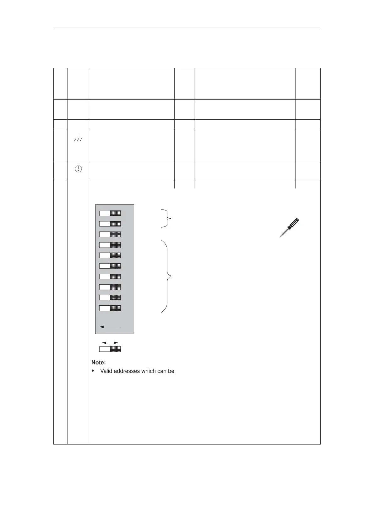
S1 – PROFIBUS node address I DIL switch, 10–pin –
OFFON
Standard setting
10
9
8
7
6
5
4
3
2
1
On/off
On/off
On/off
2
6
= 64
2
5
= 32
2
4
= 16
2
3
= 8
2
2
= 4
2
1
= 2
2
0
= 1
PROFIBUS terminating resistor
Terminating Terminating
ON on OFF off
ON on OFF off
OFF PROFIBUS communications
PROFIBUS node address
Example: 1 2
S7: ON 64 OFF 0
S6: ON 32 ON 32
S5: ON 16 OFF 0
S4: OFF 0 OFF 0
S3: OFF 0ON 4
S2: OFF 0 OFF 0
S1: ON 1ON 1
–––––––––– ––––––––––
Σ = 113 37
Note:
S Valid addresses which can be set: 3 to 126
S For the first and last physical PROFIBUS nodes, the terminating resistor must be
switched–in.
Switches 9 and 10 must always be in the same setting.
S The selected address is indicated using P918 (PROFIBUS node address).
S From SW 1.4, the following applies:
When powering–up the positioning motor, PROFIBUS node address 0 or 127 is
detected (all of the address switches are either OFF or ON); this means that the
function ”jog operation without PROFIBUS and parameterization” is activated (refer to
Chapter 5.5.11).
1) I: Input; O: Output
2 Installing and Connecting–Up
02.9906.05