2
2.4 Mounting SIMODRIVE POSMO A
2-54
E Siemens AG 2013 All Rights Reserved
SIMODRIVE POSMO A User Manual (POS1) – 08/2013 Edition
10120
10
not to scale
8 – 12
I/O cable
Shield
1) Remove cores
which are not used
1)
1)
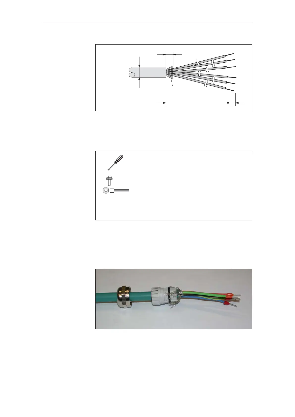
Fig. 2-21 Preparing cables for inputs/outputs
Cross–section: 4 mm
2
Thread: M5 x 10, hole
Note:
S The potential bonding conductor should be
routed as far as possible, in parallel to the
Profibus cable. This increases the PROFIBUS
noise immunity.
S It is not permissible that the protective
conductor is interrupted (refer to Chapter 2.3.2).
Torx T20
max. 3 Nm
Fig. 2-22 Potential bonding conductor and protective conductor
The following pre–assembled cable is shown in Fig. 2-23:
S The PROFIBUS cable with electronics power supply
Fig. 2-23 Example: Pre–assembled cable for PROFIBUS
Cables for
potential bonding
and protective
conductor
Example:
Cables prepared
for installation
2 Installing and Connecting–Up
02.9908.03