2
2.4 Mounting SIMODRIVE POSMO A
2-59
E Siemens AG 2013 All Rights Reserved
SIMODRIVE POSMO A User Manual (POS1) – 08/2013 Edition
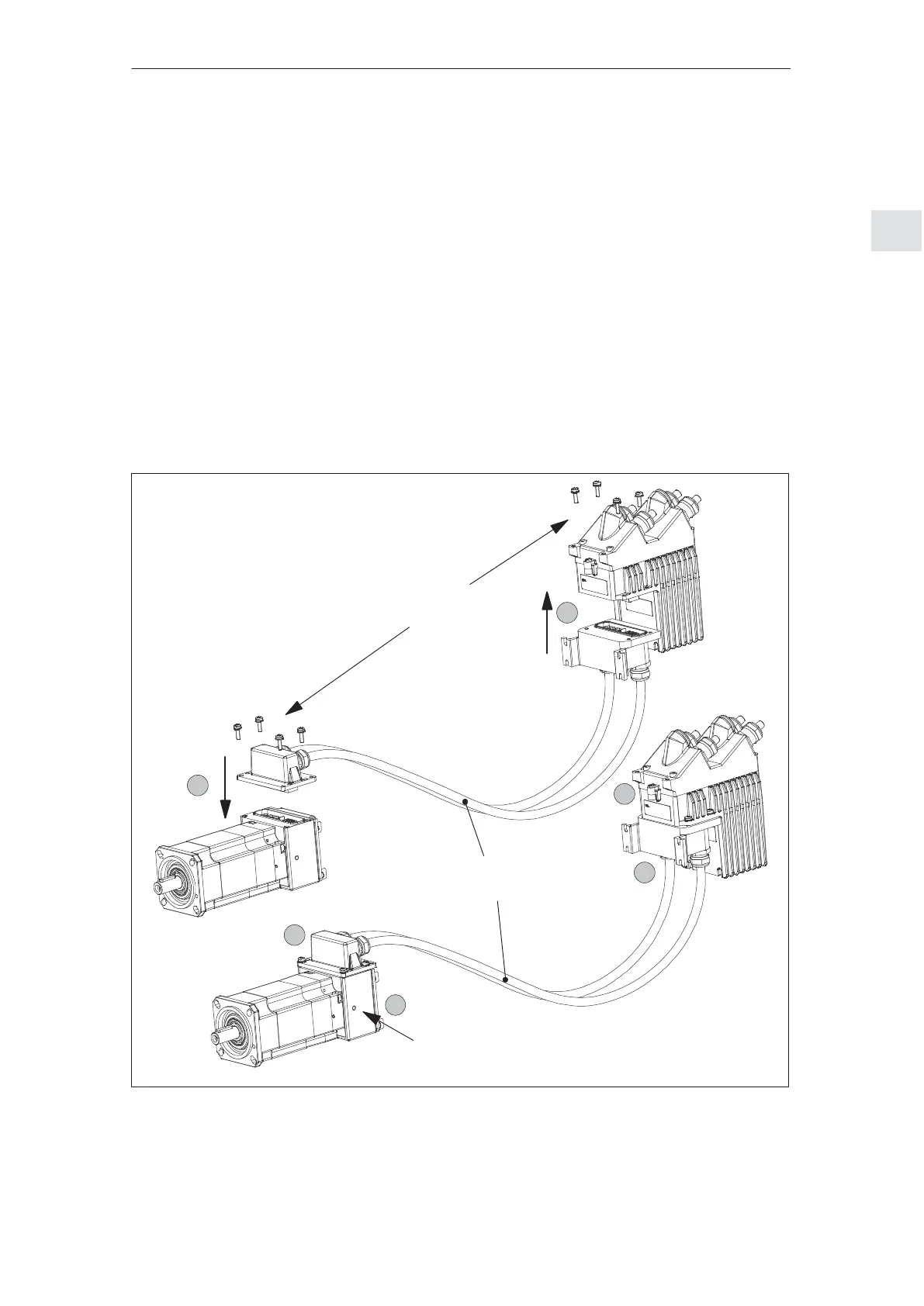
3. Insert the extension set ”separate version” POSMO A – 300 W at
the motor and drive unit.
4. Using the 4 retaining screws supplied, screw the extension set to
the motor and drive unit.
– Torque wrench (Allen key, SW 3)
– Tighten the screws diagonally
– Torque: 1.8 Nm
5. Attach the potential bonding and protective conductor (cross–
section: 4 mm
2
)
– At the drive unit: Two screw terminals (M5) on the cover
––> refer to Chapter 2.3.1
– At the motor: Two of the three screw threads (M5) for the trans-
port lugs ––> refer to Fig. 2-30
4 screws supplied loose
with the equipment
3
3
Extension set, ”separate version”
Potential bonding and protective conductor (both ends) M5 x 10
4
4
5
5
Note:
Minimum bending radius of
the cables, 100 mm
not to scale
Connector A
Connector B
Fig. 2-30 Mounting the extension set ”separate version” POSMO A – 300 W
2 Installing and Connecting–Up
02.9908.06