3.2 Commissioning the DP master
3-76
E Siemens AG 2013 All Rights Reserved
SIMODRIVE POSMO A User Manual (POS1) – 08/2013 Edition
The following data transfers in the PZD and PKW areas result from the
peripheral addresses configured in the example:
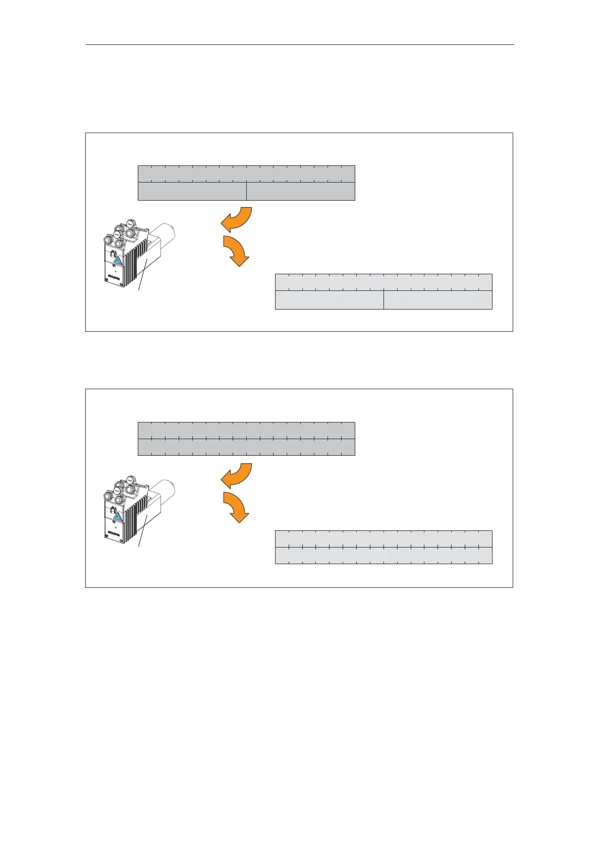
Status signals, data from the drive
PEW 264
PEW 266
Actual block number
Checkback signal byte
(RMB)
PEB 264 PEB 265
PEB 266 PEB 267
DP slave POSMO A
Note:
Description of the PZD area
––> Refer to Chapter 4.2
Status word (ZSW)
Control signals, data to the drive
Select block number Start byte (STB)
PAB 264 PAB 265
PAB 266 PAB 267
Control word (STW)
PAW 264
PAW 266
Fig. 3-2 Data transfer in the PZD area in the ”positioning” mode (P700=2) (addresses are only as
example)
Status signals, data from the drive
PEW 264
PEW 266
PEB 264 PEB 265
PEB 266 PEB 267
DP slave POSMO A
Note:
Description of the PZD area
––> Refer to Chapter 4.2
Normalization of the speed actual
values:
4000
hex
––> 1000
hex
of the
speed specified in P880
Status word (ZSW)
Control signals, data to the drive
PAB 264 PAB 265
PAB 266 PAB 267
Control word (STW)
PAW 264
PAW 266
Speed setpoint, bits 0...14, sign, bit 15
Speed actual value, bits 0...14, sign, bit 15
Fig. 3-3 Data transfer in the PZD area in the ”speed setpoint” mode (P700=1) (addresses are only as
example)
Data to/from the
drive in the PZD
and PKW areas
02.9905.03