Electrical connection
8.3 System integration
1FT2 synchronous motors for SINAMICS S120
Configuration Manual, 03/2021, A5E50645584B AA
121
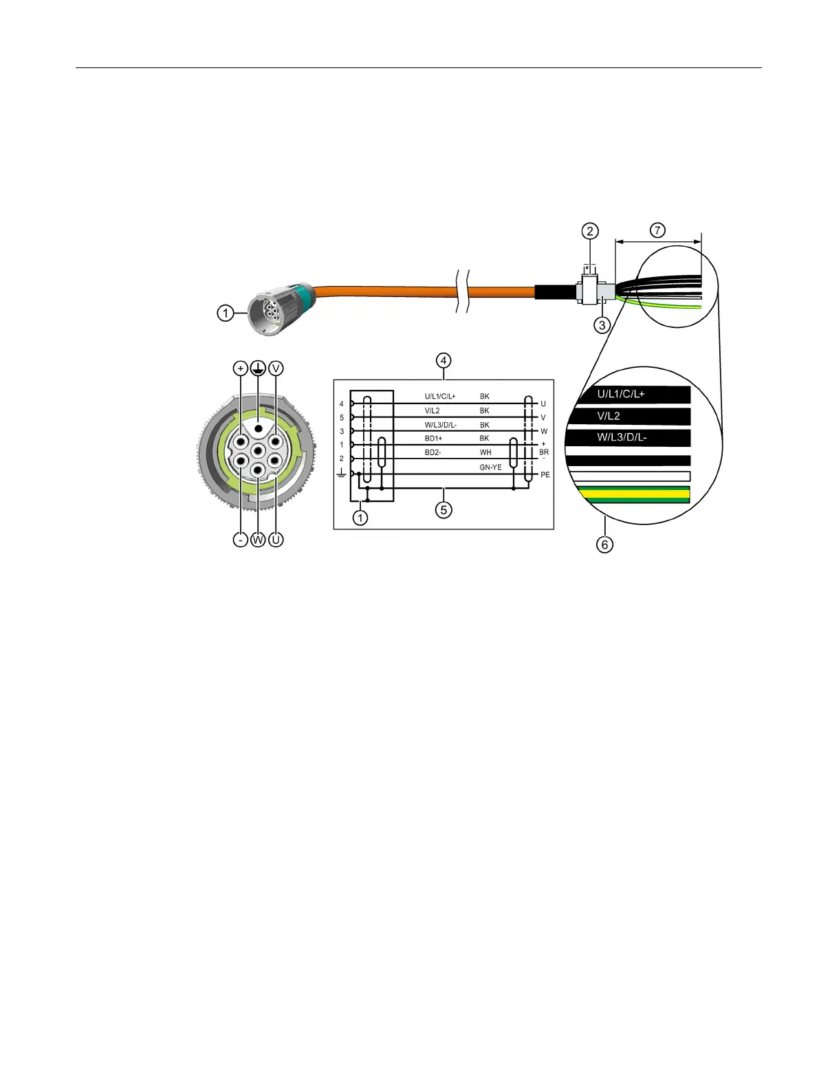
Connection diagram for connection of the 1FT2 motor to the S120 Power Module and Motor
Module Booksize and Compact with a MOTION-CONNECT cable
For connector size M17
SPEED-CONNECT connector, size M17
Terminal for the cable shield
④ Connection diagram
U; V; W = power cables, 1.5 mm
2
, each cable with separate shielding
BD1+ and BD2- = brake cable without lettering, 1.5 mm
2
, shielded together
PE = protective conductor
Recommended length of the cable ends: 105 mm