Technical data
4.4 Interfaces and performance features
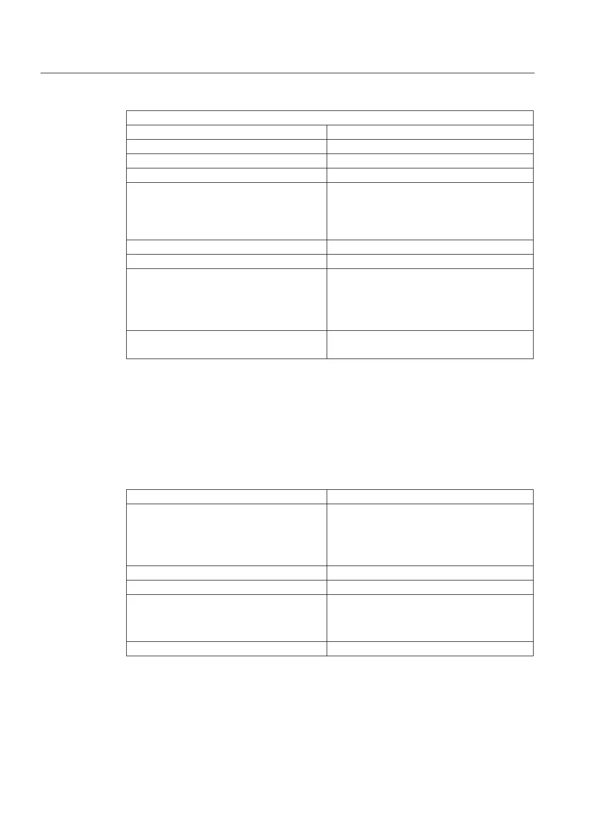
SIMOTION D410-2
66 Manual, 02/2012
If used as an output
Rated load voltage, permissible range 24 VDC, 20.4 ... 28.8 V
Galvanic isolation No
Current load, max. 500 mA per output
Residual current, max. 2 mA
Output delay, typ./max. (hardware)
1)
• 0 → 1 signal
• 1 → 0 signal
• 150 μs / 400 μs
• 75 μs / 100 μs
Cam output, resolution Typ. 125 µs
Cam output, reproducibility
3)
Switching frequency of the outputs, max.
• With resistive load
• With inductive load
• With lamp load (max. 5 W)
• 100 Hz
• 0.5 Hz
• 10 Hz
Protection Short circuit, ground fault and overload proof
Automatic restart after overload tripping
1)
Data for: V
cc
= 24 V; load 48 Ω; high ("1") = 90% V
out
; low ("0") = 10% V
out
2)
The digital inputs are protected against polarity reversal up to -30 V
3)
The information was not available at the time of going to press. For the latest information, go to
http://support.automation.siemens.com/WW/view/de/27585482.
Fail-safe digital I/Os
Table 4- 13 Technical data for fail-safe digital inputs (F-DI)
Number of inputs 3 F-DI (or as 6 DI)
Input voltage
• Rated value
• For signal "1"
• For signal "0"
1)
• 24 VDC
• 15 ... 30 V
• -3 ... +5 V
Electrical isolation
2)
Yes (via optocoupler)
Current consumption typical at 1 signal level 6 mA at 24 V
Input delay, typical (hardware)
• 0 → 1 signal
• 1 → 0 signal
• 50 μs
• 150 μs
Protection Short circuit, ground fault and overload proof
1)
The digital inputs are protected against polarity reversal up to -30 V
2)
Reference potential for DI 16, DI 18, DI 20 and DO 16 is terminal M1 (X120, X130)

 Loading...


