Technical data
4.4 Interfaces and performance features
SIMOTION D410-2
Manual, 02/2012
65
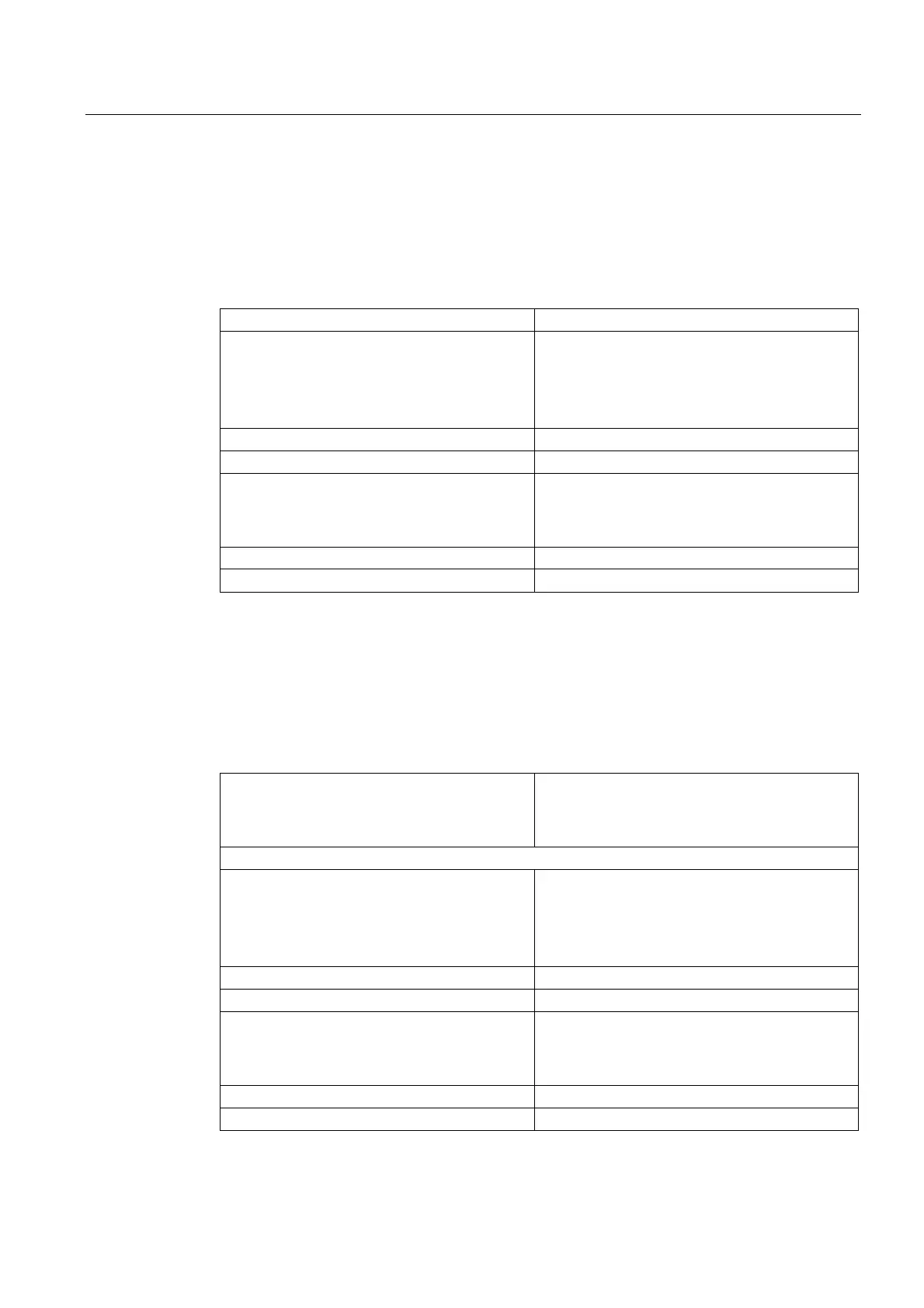
4.4.3 Onboard I/Os
Digital inputs
Table 4- 11 Technical data for digital inputs
Number of inputs 5
Input voltage
• Rated value
• For signal "1"
• For signal "0"
2)
• 24 VDC
• 15 ... 30 V
• -3 ... +5 V
Electrical isolation
1)
Yes (via optocoupler)
Current consumption typical at 1 signal level 6 mA at 24 V
Input delay, typical (hardware)
• 0 → 1 signal
• 1 → 0 signal
• 50 μs
• 150 μs
Permissible quiescent current 2 mA
Protection Protected against polarity reversal
1)
Reference potential for DI 0 ... DI 3 is terminal M2 (X121, X130),
reference potential for DI 22+ is terminal DI 22- (X130)
2)
The digital inputs are protected against polarity reversal up to -30 V
Digital I/Os
Table 4- 12 Technical data regarding the digital I/Os with adjustable parameters
Number of digital I/Os 8
• Max. 8 as measuring input inputs
• Max. 8 as cam outputs
If used as an input
Input voltage
• Rated value
• For signal "1"
• For signal "0"
2)
• 24 VDC
• 15 ... 30 V
• -3 V ... +5 V
Galvanic isolation No
Current consumption typical at 1 signal level 5 mA at 24 V
Input delay, typ. (hardware):
• 0 → 1 signal
• 1 → 0 signal
• 5 μs
• 50 μs
Measuring input, resolution 1 μs
Measuring input, reproducibility 5 μs