Technical data
4.4 Interfaces and performance features
SIMOTION D410-2
Manual, 02/2012
67
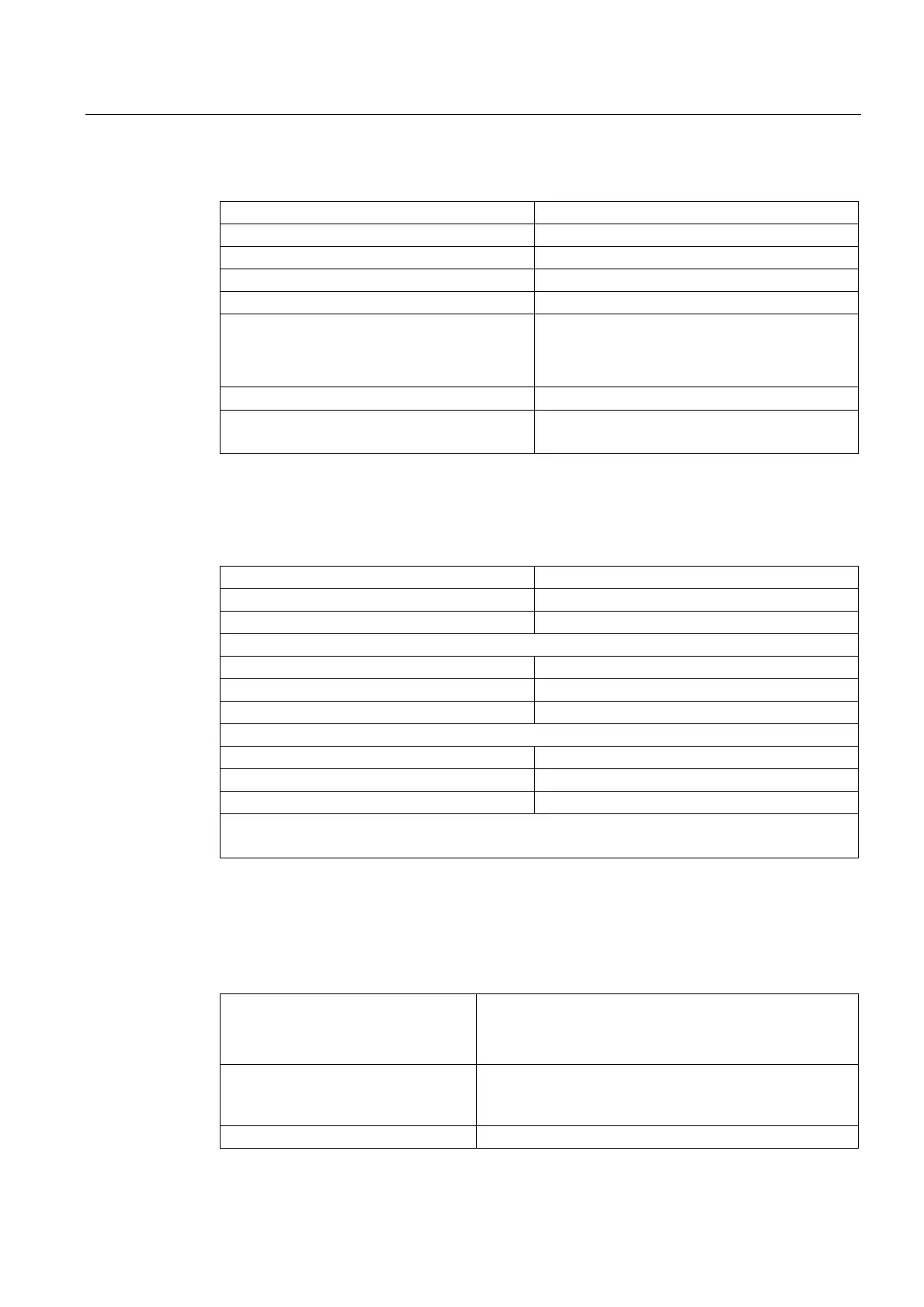
Table 4- 14 Technical data for fail-safe digital output (F-DO)
Number of outputs 1 F-DO (or as 1 DO)
Rated load voltage, permissible range 24 VDC, 20.4 ... 28.8 V
Electrical isolation Yes (via optocoupler)
Current load, max. 500 mA
Residual current, max. 2 mA
Output delay, typ. (hardware)
• 0 → 1 signal
• 1 → 0 signal
• 150 μs / 400 μs
• 75 μs / 100 μs
Permissible quiescent current 2 mA
Protection Short circuit, ground fault and overload proof
No automatic restart after overload tripping
Analog input
Table 4- 15 Technical data for the analog input
Number of inputs 1
Galvanic isolation No
Common-mode range -12 ... +12 V
When used as analog voltage input
Input voltage range -10 ... +10 V
Resolution 12 bit + sign (based on ± 11
V)1)
Input resistance (R
i
) > 100 kΩ
When used as analog current input
Input current range -20 ... +20 mA
Resolution 11 bit + sign (based on ± 22 mA)
1)
Input resistance (R
i
) 250 Ω
1)
The maximum controllable area is approx. ± 11 V or ± 44 mA
The resolution refers to the specified area (irrespective of the engineering settings).
4.4.4 Onboard encoder interface
Table 4- 16 Technical data of the encoder interface
Encoder interface
• TTL or HTL incremental encoders (with adjustable
parameters)
• Absolute encoder
Power supply 24 VDC / 0.35 A or
5 VDC / 0.35 A
Short-circuit and overload proof
Limit frequency 500 kHz
 Loading...


