Spare parts / accessories
6.4 TM54F terminal module
SIMOTION D410-2
Manual, 02/2012
79
Interfaces
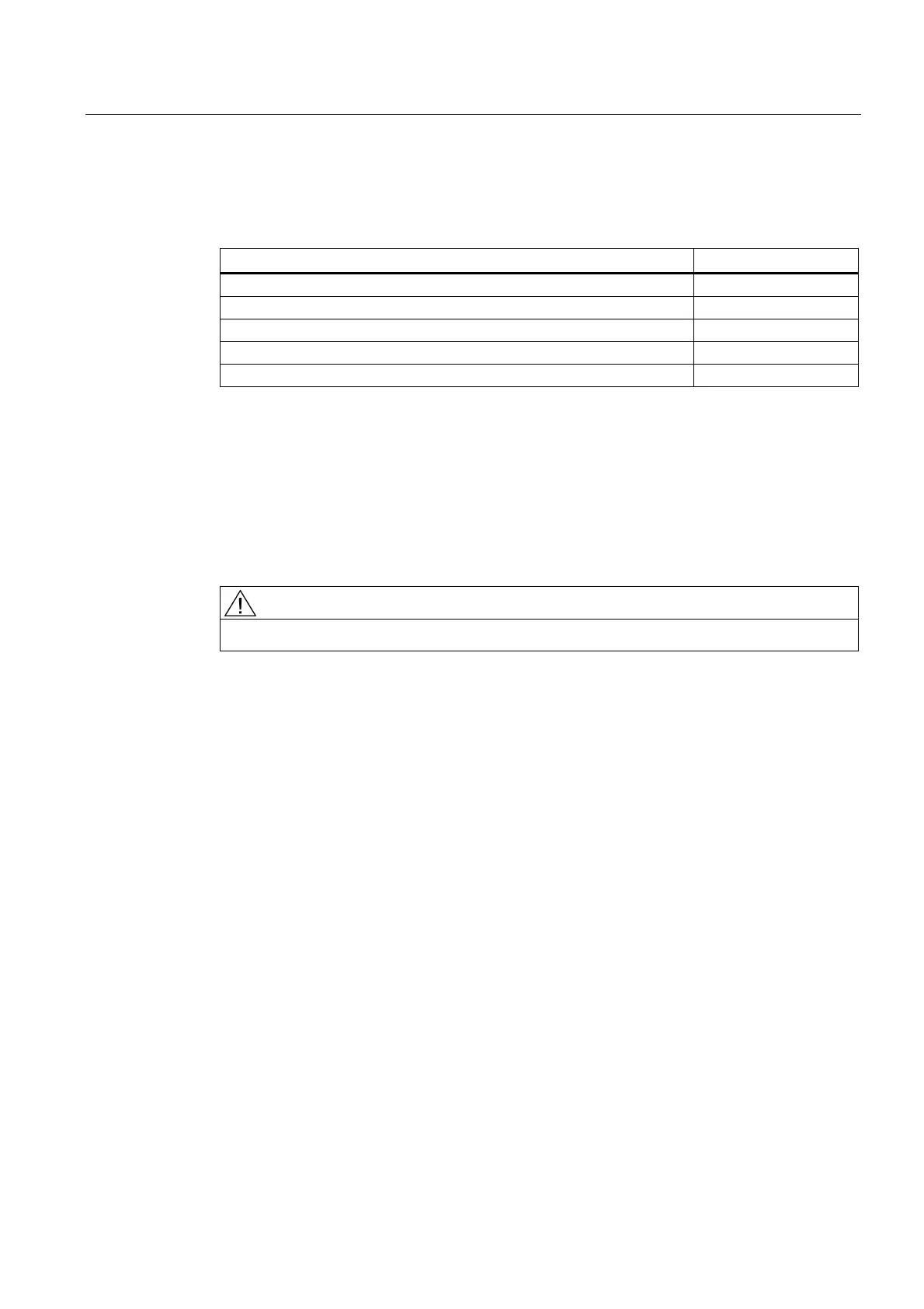
Table 6- 4 The following terminals are located on the TM54F:
Type Number
Fail-safe digital outputs (F-DO)
1)
4
Fail-safe digital inputs (F-DI)
2)
10
Sensor power supplies, can be made dynamic
3), 4)
2
Sensor power supply, cannot be made dynamic
3)
1
Digital inputs for testing the F-DO at test stop 4
1)
A fail-safe digital output consists of a P/M-switching output as well as a digital input for reading
back the switching state.
2)
A fail-safe digital input consists of two digital inputs.
3)
Sensors: Fail-safe devices for commanding and detecting, such as emergency stop pushbuttons
and safety locks as well as position switches and light arrays / light curtains.
4)
Dynamic response: The sensor power supply is switched on and off during test stop for testing the
sensors, the cable routing, and the evaluation electronics of TM54F.
CAUTION
The 50 mm clearances above and below the component must be observed.
Additional references
You find detailed information about the TM54F terminal module in the
SINAMICS S120
Safety Integrated
Function Manual.
See also
DRIVE-CLiQ interface (Page 34)
 Loading...


