3.2 Operator controls
3.2.1 Service selector switch
Layout
SIMOTION D410-2 provides a service selector switch (SVC) behind the blanking cover in the
lower area of the front panel.
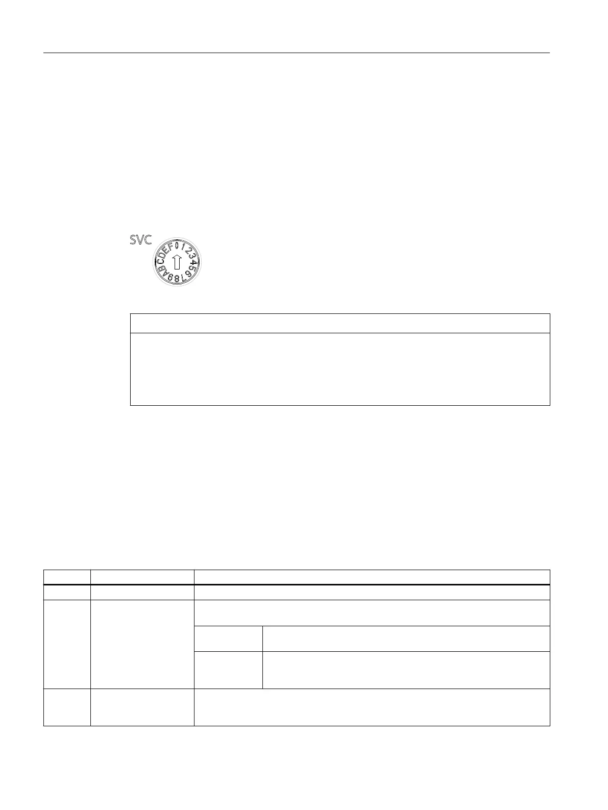
Figure 3-2 Service selector switch, switch position "0"
NOTICE
Damage from electrostatic discharge
The rotary switch can be destroyed by static electricity.
Operate the rotary switch only with an insulated screwdriver.
Comply with the ESD rules.
Function
The service selector switch is used to select service functions.
In "normal" operation, this switch must remain in the "0" position.
The following table shows the possible positions of the service selector switch. The service
selector switch positions are explained in the order in which they are arranged on the
SIMOTION D410-2. The service functions can generally be used in any set operating mode.
Table 3-1 Switch positions of the service selector switch
Position Service mode Meaning
0 No service/diagnostic function activated
1
or
A → 1
Delete/restore non-vola‐
tile SIMOTION data
The non-volatile SIMOTION data of the SIMOTION D410‑2 is rst deleted and then re‐
stored with the contents of the PMEMORY backup le.
Position "1" The data backed up with the system function _savePersistentMemor‐
yData is preferably restored
Position
"A" → "1"
(as of V4.4)
The data backed up by service selector switch position "D" / Web server /
DIAG pushbutton are preferably restored
8 Web server in security
level low
Switches the SIMOTION IT Web server to Security Level Low for 120 minutes.
You will nd detailed information in the SIMOTION IT Diagnostics and Conguration
Diagnostics Manual.
Operator control (hardware)
3.2 Operator controls
SIMOTION D410-2
40 Equipment Manual, 07/2021, A5E33446720B

 Loading...


