Interface assignment
Table 4-11 Assignment of the ports X150 P1 to P2
Representation Pin Name Description
1 TXP Send data +
2 TXN Send data -
3 RXP Receive data +
4 - Reserved, do not use
5 - Reserved, do not use
6 RXN Receive data -
7 - Reserved, do not use
8 - Reserved, do not use
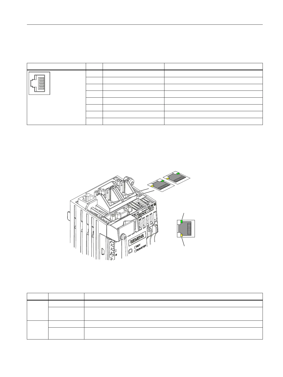
LED displays of the PROFINET interface
The PROFINET ports X150 P1 and P2 have two integrated LEDs each for displaying link and
activity.
'LVSOD\
'LVSOD\
$&7
/,1.
Figure 4-1 PROFINET ports of the D410-2 DP/PN
Table 4-12 State of the Link and Activity LEDs
LED State Meaning
LINK OFF No or faulty connection
Lights up green Transmission rate 10 or 100 Mbit/s:
A dierent device is connected to port x and a physical connection exists
ACT OFF No data exchange
Flickers yellow Data exchange:
Data is being received or sent at port x.
Interfaces
4.4 PROFINET IO interface (SIMOTION D410-2 DP/PN only)
SIMOTION D410-2
Equipment Manual, 07/2021, A5E33446720B 53

 Loading...


