NOTICE
Destruction of the encoder electronics
Operation of a 5 V encoder on the 24 V encoder supply may result in the destruction of its
electronic components!
Make sure that you can operate the connected encoder on a 24 V power supply (e.g. HTL
encoder). This setting can be set in the expert list of the drive in parameter p0400 and in the
following parameters.
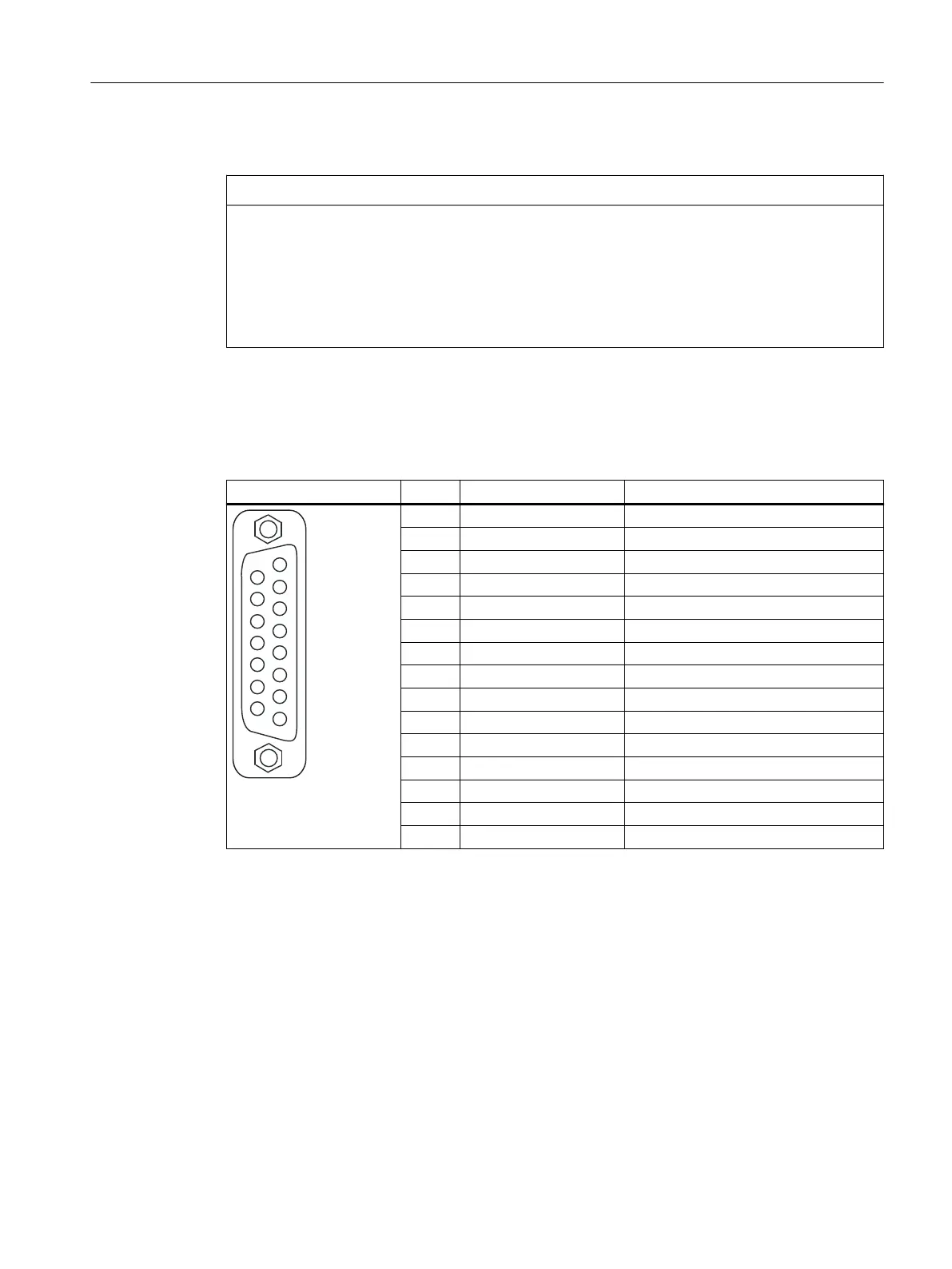
Interface assignment
Table 4-14 Interface assignment X23
Representation Pin Name Description
1 +Temp KTY, PT1000 or PTC input
2 SSI_CLK SSI clock positive
3 SSI_XCLK SSI clock negative
4 P_Encoder 5 V / 24 V Encoder power supply
5 P_Encoder 5 V / 24 V Encoder power supply
6 P_Sense Sense input encoder power supply
7 G_Encoder (G) Ground for sensor power supply
8 -Temp (G) Ground for KTY, PT1000 or PTC
9 G_Sense (G) Ground sense input
10 RP R track positive
11 RN R track negative
12 BN B track negative
13 BP B track positive
14 AN_SSI_XDAT A track negative / SSI data negative
15 AP_SSI_DAT A track positive / SSI data positive
For Pin 1 / Pin 8: The associated temperature channel (T1) can be assigned parameters as an individual
channel or together in combination with the second temperature channel (T2) at interface X120.
(For parameterization, see the SINAMICS S120 Commissioning Manual).
For Pin 6 / Pin 9: At an encoder supply of 5 V, the voltage drops on the encoder supply cables are recorded
and compensated by means of the sense cables. For this purpose, the sensor supply is corrected on the
SIMOTION D410-2.
Interfaces
4.5 Encoder interface (HTL/TTL/SSI)
SIMOTION D410-2
Equipment Manual, 07/2021, A5E33446720B 55

 Loading...


