X121
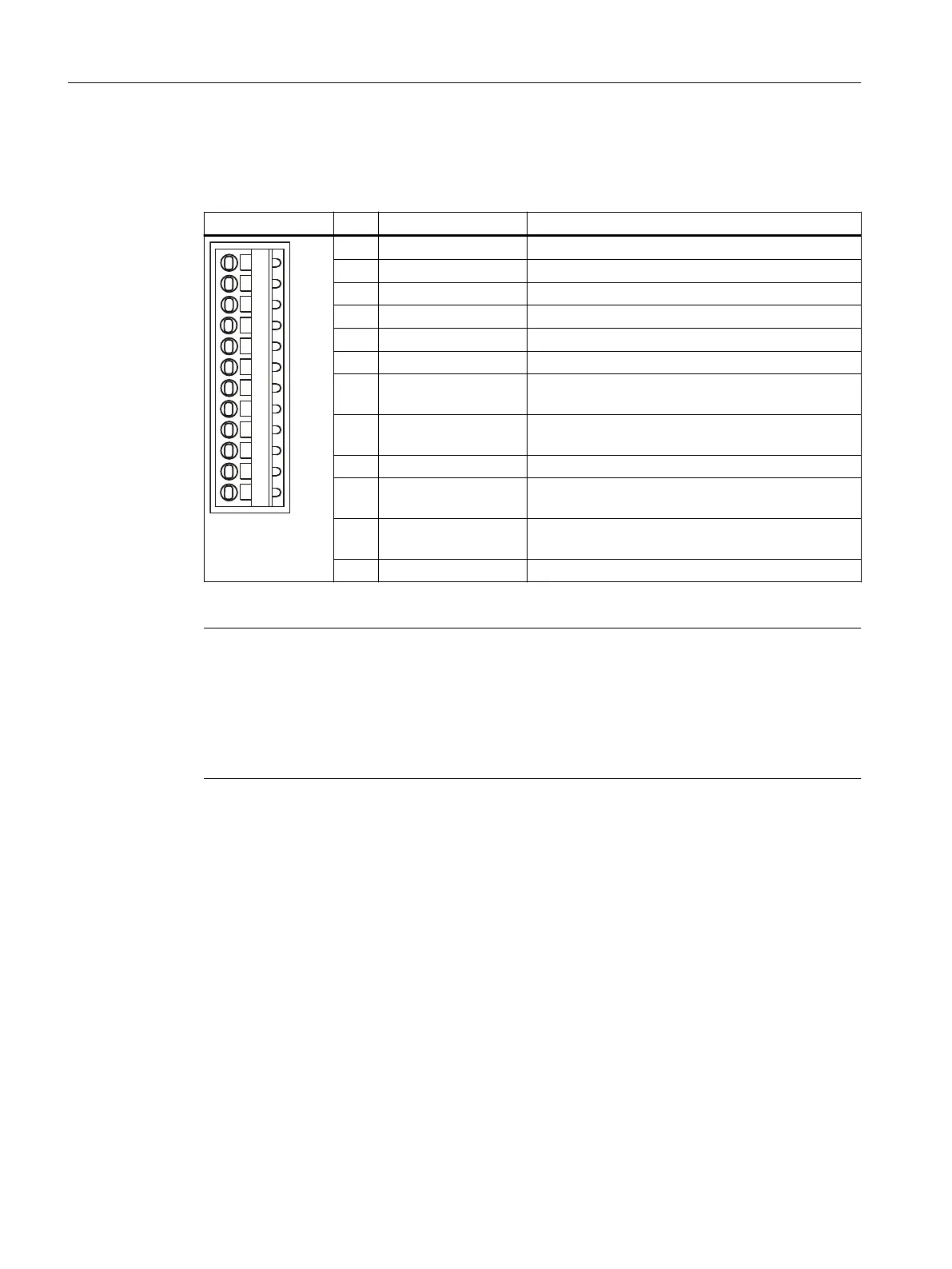
Table 4-19 Interface assignment X121
Representation Pin Designation Notes
1 DI 0 Isolated digital input 0
2 DI 1 Isolated digital input 1
3 DI 2 Isolated digital input 2
4 DI 3 Isolated digital input 3
5 M2 Ground reference for DI 0 … DI 3
6 M Ground reference of the electronics
1)
7 DI/DO 8 High-speed digital I/O 8,
not isolated
8 DI/DO 9 High-speed digital I/O 9,
not isolated
9 M Ground reference of the electronics
1)
10 DI/DO 10 High-speed digital I/O 10,
not isolated
11 DI/DO 11 High-speed digital I/O 11,
not isolated
12 M Ground reference of the electronics
1)
1)
Reference potential for the digital inputs/outputs and analog input
Note
An open input is interpreted as "low".
The use of the digital inputs (DI 0 ... DI 3) requires terminal M2 be connected. This is achieved
by:
• Providing the reference ground of the digital inputs, or
• a jumper to terminal M. This removes the electrical isolation for these digital inputs.
Interfaces
4.6 Digital I/Os / temperature sensor / analog input
SIMOTION D410-2
62 Equipment Manual, 07/2021, A5E33446720B

 Loading...


