Fail-safe digital inputs/outputs
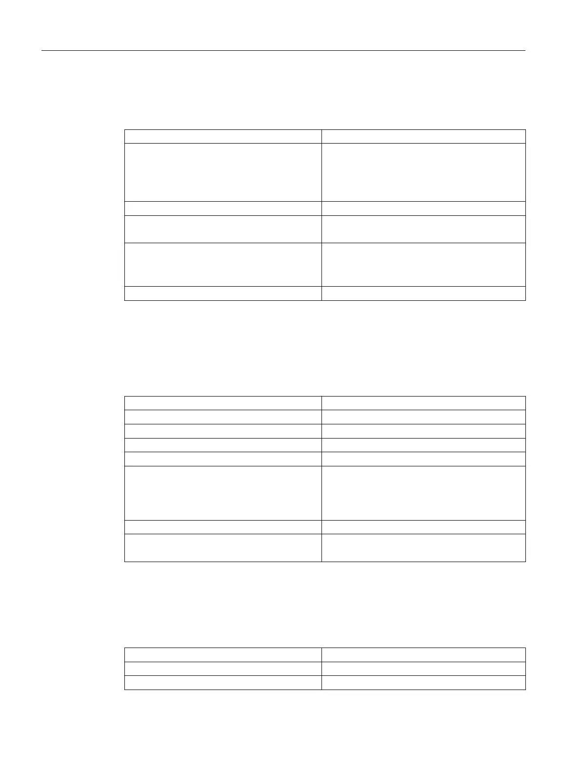
Table 5-14 Technical data for fail-safe digital inputs (F-DI)
Number of inputs 3 F-DI (or as 6 DI)
Input voltage
• Rated value
• For signal "1"
• For signal "0"
1)
• 24 VDC
• 15 … 30 V
• -3 … +5 V
Electrical isolation
2)
Yes (via optocoupler)
Current consumption typical at 1 signal level 3.5 mA at 24 V
5 mA at 24 V
3)
Input delay, typical (hardware)
• Signal "0" → "1"
• Signal "1" → "0"
• 50 μs
• 150 μs
Protection Short circuit, ground fault and overload proof
1)
The digital inputs are protected against polarity reversal up to -30 V
2)
Reference potential for DI 16, DI 18, DI 20 and DO 16 is terminal M1 (X120, X130)
3)
Up to and including hardware version "C" for D410-2 DP or "B" for D410-2 DP/PN
Table 5-15 Technical data for fail-safe digital output (F‑DO)
Number of outputs 1 F-DO (or as 1 DO)
Rated load voltage, permissible range 24 VDC, 20.4 ... 28.8 V
Electrical isolation Yes (via optocoupler)
Current load, max. 500 mA
Residual current, max. 2 mA
Output delay time,
typ./max. (hardware)
1)
• Signal "0" → "1"
• Signal "1" → "0"
• 150 μs / 400 μs
• 75 μs / 100 μs
Permissible quiescent current 2 mA
Protection Short circuit, ground fault and overload proof
Automatic restart after overload tripping
1)
Data for: V
cc
= 24 V; load 48 Ω; high ("1") = 90% V
out
; low ("0") = 10% V
out
Analog input
Table 5-16 Technical data for the analog input
Number of inputs 1
Galvanic isolation No
Common-mode range -12 … +12 V
Technical data
5.4 Interfaces and performance features
SIMOTION D410-2
90 Equipment Manual, 07/2021, A5E33446720B

 Loading...


