4.10.3 Terminal strips
Terminal strips for FSAA…FSC with wiring example
9RSWLRQDOSRZHUVXSSO\W\SLFDOO\$
5HIHUHQFHIRUWHUPLQDOb
9RXWSXWPD[P$
5HIHUHQFHIRUWHUPLQDOVDQG
$QDORJLQSXW99P$P$
5HIHUHQFHIRUWHUPLQDOb
$QDORJRXWSXW99P$P$
5HIHUHQFHIRUWHUPLQDOVDQG
'LJLWDORXWSXWPD[$9'&
7HPSHUDWXUHVHQVRU37&.7<3WELPHWDO
5HIHUHQFHIRUWHUPLQDOVDQG
5HIHUHQFHIRUWHUPLQDOVDQG
5HIHUHQFHIRUWHUPLQDOVDQG
'LJLWDORXWSXW
PD[$9'&
9RXWSXWPD[P$
'LJLWDOLQSXWVIRUFRQWDFWVVZLWFKLQJWR3RU1
ORZ9KLJK!9PD[9
;
;
;
;
9,1
*1',1
9287
*1'
$,
$,
$2
*1'
'2
'2
702725
702725
*1'
',&20
',&20
',
',
',
',
',
',
'212
'2&20
'21&
9287
ุN˖
9
H[W
*1'
H[W
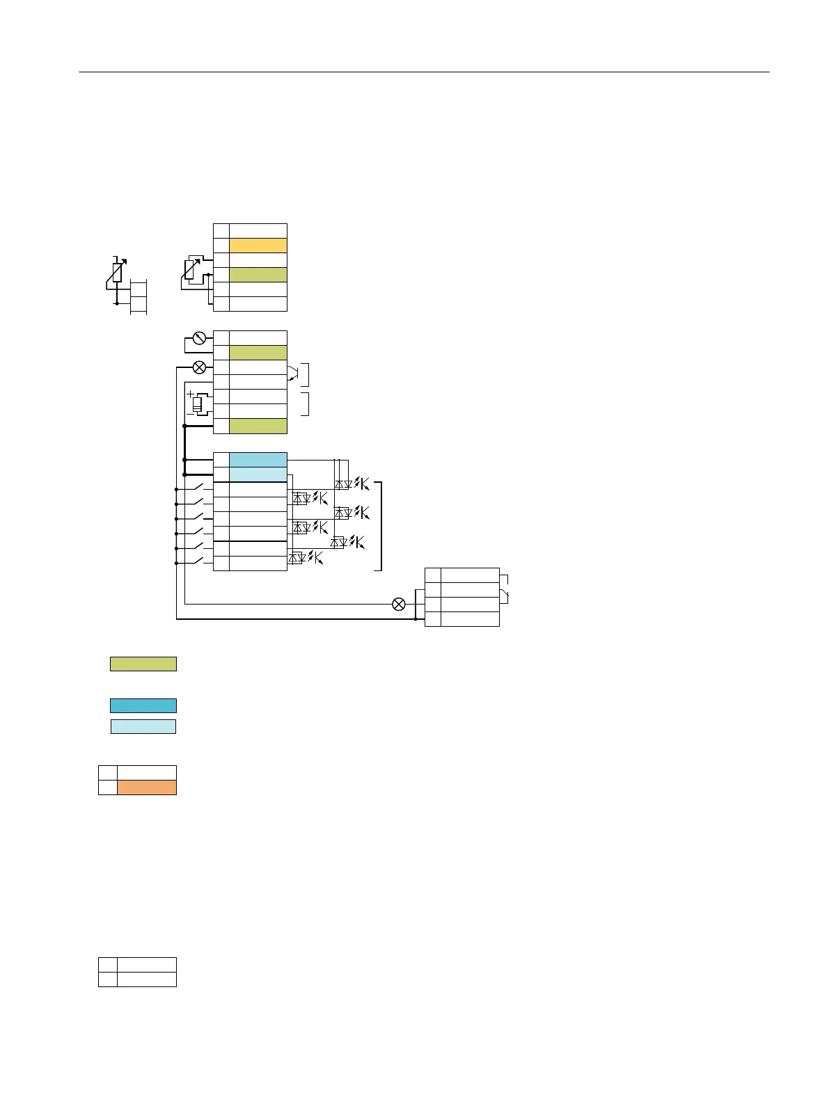
Figure4-33 Wiring example of the digital inputs with the internal converter 24 V power supply
All terminals with the reference potential "GND" are connected to each other inside the
converter.
Reference potentials "DI COM1" and "DI COM2" are electrically isolated from "GND".
→ if, as described above, you use the 24‑V power supply from terminal 9 to supply the digital
inputs, then you must connect "GND" with "DICOM1" and "DICOM2" at the terminals.
When an optional 24-V power supply is connected to terminals 31, 32, the Control Unit
remains in operation even after the Power Module has been disconnected from the line
supply. The Control Unit thus maintains eldbus communication, for example.
→ for terminals 31, 32 only use a 24 VDC power supply with PELV (Protective Extra Low
Voltage).
→ for applications in the USA and Canada: Use a 24 VDC power supply, NEC Class 2.
→ connect the 0 V of the power supply with the protective conductor.
→ if you also wish to use the power supply at terminals 31, 32 for the digital inputs, then you
must connect "DICOM1/2" and "GNDIN" with one another at the terminals.
For the analog input, you can use the internal 10-V power supply or an external voltage
source. Typical current consumption: 10mA…20mA.
Installing
4.10Connecting the interfaces for the converter control
SINAMICS G120C Converters
Operating Instructions, 02/2023, FW V4.7 SP14, A5E34263257B AK 85
 Loading...


