Detailed description
2.1 Axes
Basic logic functions: Axes, coordinate systems, frames (K2)
Function Manual, 11/2006, 6FC5397-0BP10-2BA0
33
%
$
$
%
'
$
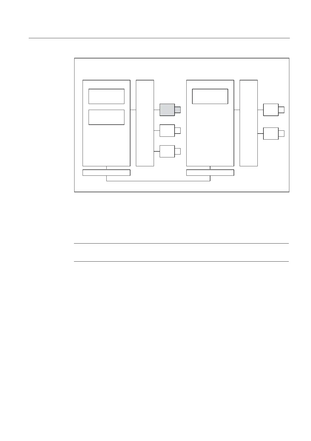
' 1&81&8
&KDQQHO
&KDQQHO
&KDQQHO
/LQNFRPPXQLFDWLRQ
/LQNPRGXOH+: /LQNPRGXOH+:
Figure 2-6 Overview of link axes
The link axes are described in
References:
/FB2/ Function Manual, Expansion Functions; Multiple Operator Panels on Multiple NCUs,
Distributed Systems (B3)
Note
The link axis functionality is currently not available with the SINUMERIK 840Di.
Axis container
An axis container is a circular buffer data structure, in which local axes and/or link axes are
assigned to channels. The entries in the circular buffer can be shifted cyclically.
In addition to the direct reference to local axes or link axes, the link axis configuration in the
logical machine axis image also allows references to axis containers. This type of reference
consists of:
• Container number
• a slot (circular buffer location within the container)
 Loading...


