© Siemens AG All rights reserved. SINUMERIK, Manual, 5-axis machining
General information on workpiece production
2.3
21
2.3 Program structure for 5-axis machining
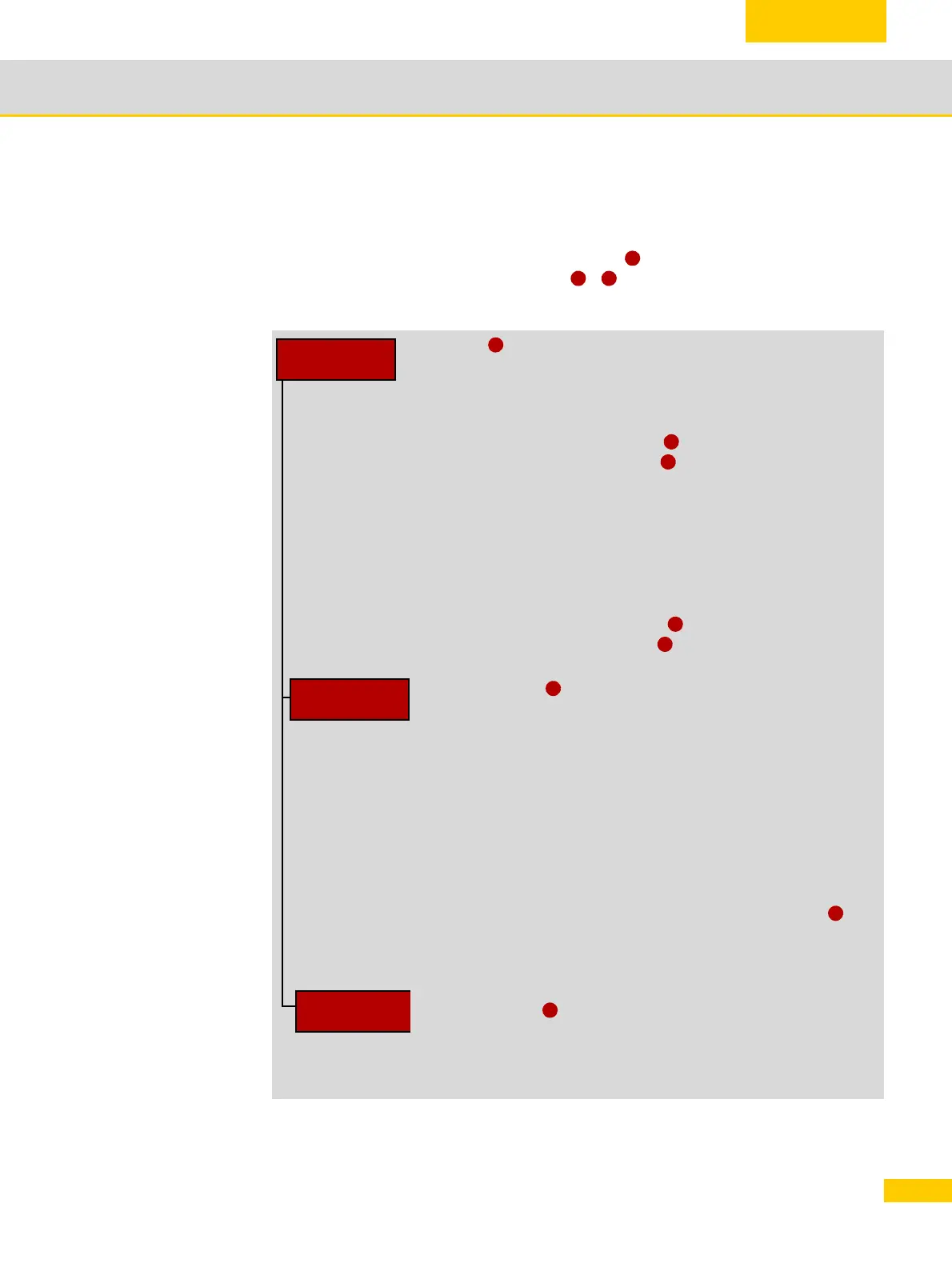
Recommendation for a practical program structure with CYCLE832
For machining purposes, a main program is generated that includes all technology data. The
main program calls one or more subprograms , that contain the workpiece's geometry
data. The tool change defines how the content is divided into subprograms.
Example
1
2 3
Call.MPF
N10
N20
N30
N40
N50
N60
T1 D1
M6
M3 S15000
G54
CYCLE832 (0.05,112103)
EXTCALL "CAM_Rough"
; Tool change
; High-speed settings
; All programs should
; be located in one
; directory. If this is not
; the case, then the
; paths must be
; specified.
N70
N80
N90
N100
N110
N120
T2 D1
M6
M3 S20000
CYCLE832 (0.005,112101)
EXTCALL "CAM_Finish"
M30
; Tool change
CAM_Rough.SPF
N1
N2
N3
N4
N17
...
N5046
N5047
...
N5051
...
N6582
N6583
N6584
G90
G0 X0 Y0 Z10
G1 Z0 F500
G1 X-1.45345 Y0.67878 F10000
G1 X-1.81412 Y0.84245
G1 X-4.11845 Y-11.44212
G0 Z10
G1 Z-2.13247 A3=0.34202 B3=0 C3=0.93969 F5000
G1 X7.60978 Y3.55541 A3=0.34202 B3=-0 C3=0.93969
G0 Z50 A3=0.34202 B3=-0 C3=0.93969
M17
CAM_Finish.SPF
N1
N2
....
N7854
G90
G0 X0 Y0 Z10 A3= B3= C3=
.......
M17
Main program
Subprogram
Subprogram
1
4
5
4
5
2
6
3

 Loading...


