© Siemens AG All rights reserved. SINUMERIK, Manual, 5-axis machining
General information on workpiece production
2.6
27
2.6 Measure tool in JOG
When executing a program, the various tool geometries must be taken into account. These are
stored as tool offset data in the tool list. When the tool is called, the control considers the tool off-
set data.
You can determine the tool offset data (i.e. the length and radius or diameter) manually, semi-
automatically, or automatically in JOG mode using a dynamometer.
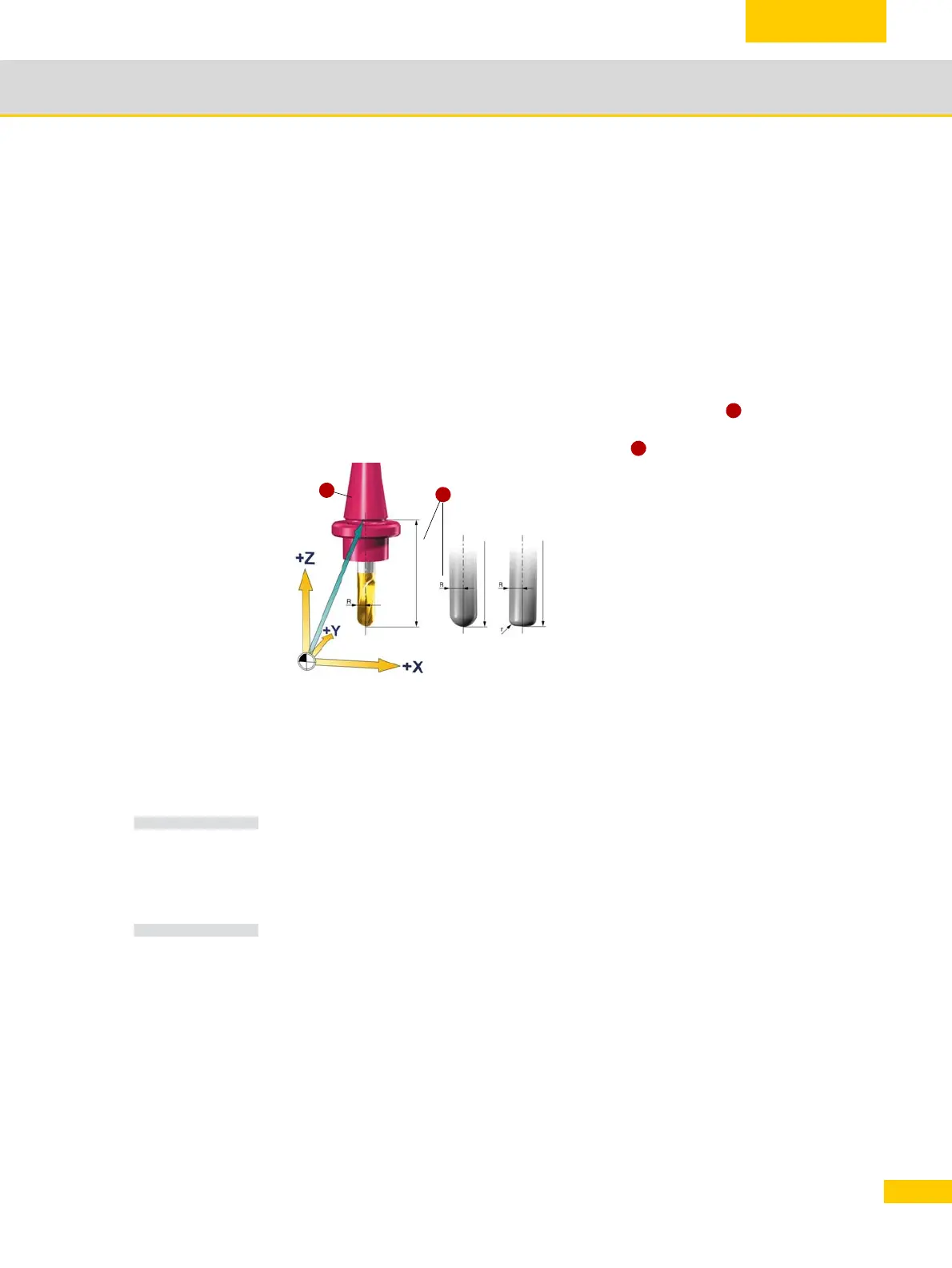
2.6.1 Tool reference point
CAM systems define the position of the TCP differently depending on the tool shape. For
Siemens controls, it is assumed that the TCP is at the tool tip. If the CAM system specifies
a different TCP position then this difference must be taken into account when specifying
the tool length.
Coordinate the following with the CAM programmer: To avoid significant tool deflection,
the CAM programmer should keep the tool length as short as possible.
The tool magazine is loaded as usual, tool
numbers T1, T2 etc. are entered into the
tool table and the tools are assigned a tool off-
set D consisting of radius "R" and length
"L1".
The CAM system already takes into account
the tool diameter when the geometry program
is being created. The calculated tool path
refers to the miller center point (center point
path).
This means that to measure the length of the
tool, you must use the same reference point
(TCP) as the CAM system. For the purpose of
determining the tool length, always remember
to check the reference point the CAM pro-
grammer used to measure L1. The TCP can
either be located at the tool tip or further
upwards in the milling tool - e.g. for radius end
mills at the center of the radius.
1
TCP = Tool Center Point
TCP TCP TCP
T1
L1
L1 L1
Taper base
2
1
2
NOTE
NOTE

 Loading...


