Key functions for 5-axis machining
3.7
© Siemens AG All rights reserved. SINUMERIK, Manual, 5-axis machining
74
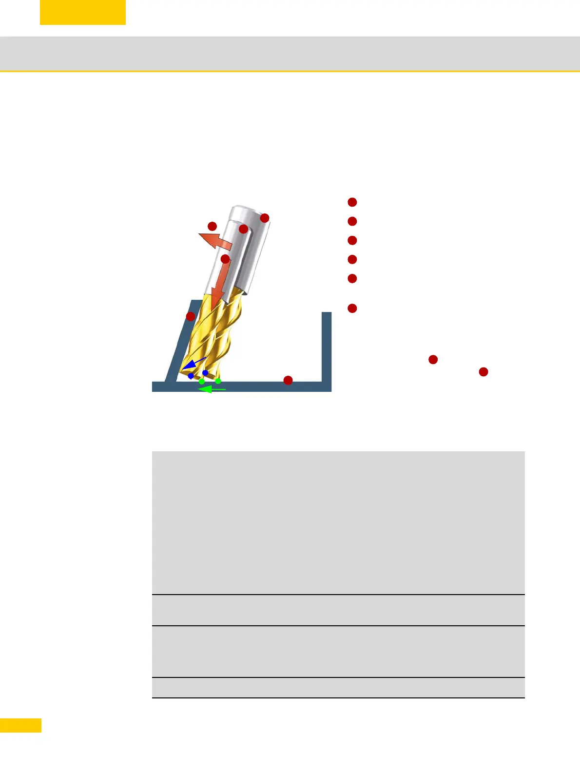
Influence of tool radius compensation with 5-axis circumferential milling, taking
into account the limitation surface (CUT3DCC)
Imagine that a pocket needs to be created using a smaller milling cutter. The side wall is not per-
pendicular to the floor surface. The control supports tool radius compensation with a smaller tool.
A typical application involving this function relates to structural components within the aviation
industry.
Circumferential milling
Explanation of the commands
Standard tool (tool from CAM)
Tool with smaller radius
Machining surface, inner surface
Limitation surface of pocket floor
Compensation in relation to machining
surface
Compensation in relation to limitation sur-
face
The control recognizes the fact that it is not
just a question of compensating in the machin-
ing surface direction , but also of making
an adjustment in the tool direction , so that
the point of action (green) is at the same level
as the pocket floor. This results in a shift in the
TCP (blue) in the direction of the pocket floor.
G40 Deactivation of all variants
G41 Activation for circumferential milling, compensation direction left
G42 Activation for circumferential milling, compensation direction right
G450 Circles at external corners (all compensation types)
G451 Intersection method at external corners (all compensation types)
2 ½D circumferential milling
CUT2D 2 1/2D COMPENSATION with compensation plane determined
using G17 – G19
CUT2DF 2 1/2D COMPENSATION with compensation plane determined
using a frame
3D circumferential milling
CUT3DC Compensation perpendicular to path tangent and tool orientation
1
2
3
5
6
4
1
2
3
4
5
6
5
6

 Loading...


