4.2 Illustration
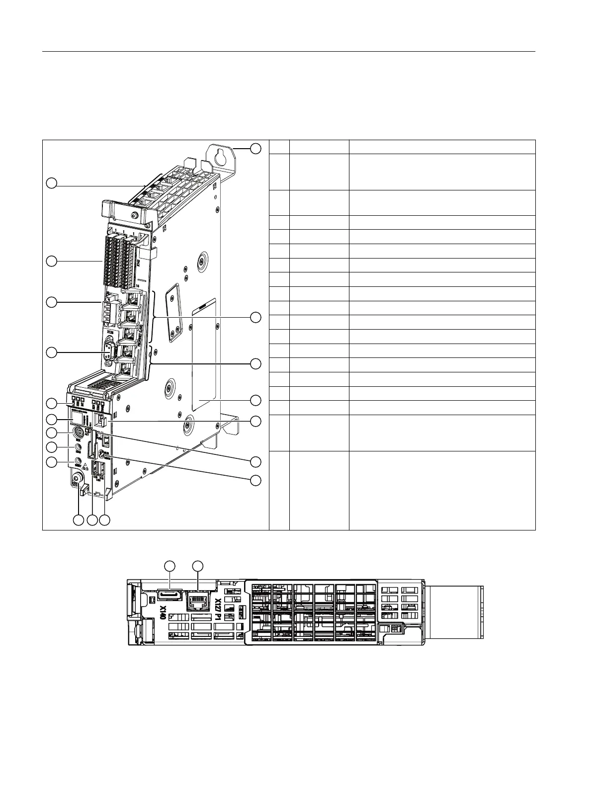
The following diagram shows an NCU with its interfaces, operating control and display elements
(fault and status displays).
① - Spacer
② X150 P1 R
X150 P2 R
X160 P1
3 PROFINET IO interfaces
③ X120
X130
2 Ethernet interfaces
④ - Type plate 1
⑤ - 7-segment display
⑥ X55 Slot for an SD card
⑦ - PLC mode selector switch (toggle switch)
⑧ X135 USB interface
⑨ X125 USB interface
⑩ - Functional grounding
⑪ - Reset button
⑫ - Diagnostics button
⑬ - NCK commissioning switch (rotary switch)
⑭ - Type plate 2
⑮ - LED displays
⑯ X126 PROFIBUS DP interface
⑰ X124 Power supply
⑱ X122
X132
X142
Digital inputs and outputs
⑲ X100 - X103 4 DRIVE-CLiQ interfaces
Representation of the NCU
① X140 Service socket (DisplayPort socket)
② X127 PN/IE Ethernet interface
Figure 4-1 NCU lower side
Description
4.2 Illustration
NCU 1740
28 Equipment Manual, 10/2021, A5E51087503B AA
 Loading...


