In the "Default setting" column, the signals for which the associated SINAMICS parameters are set when
conguring a SINAMICS device are marked with "x".
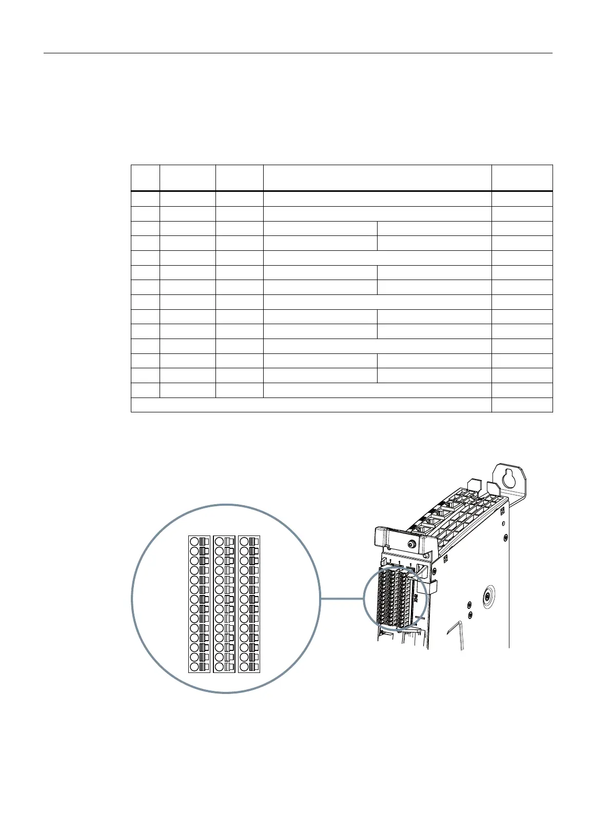
Table 8-20 X142 digital inputs/outputs
Pin Signal
name
Signal
type
Meaning Default set‐
ting
1 - - Reserved, do not use ---
2 - - Reserved, do not use ---
3 IN/OUT0 B Digital NC input 1 $A_IN[1] xed
4 IN/OUT1 B Digital NC input 2 $A_IN[2] xed
5 M GND Ground for I0 - I7 ---
6 IN/OUT2 B Digital NC input 3 $A_IN[3] xed
7 IN/OUT3 B Digital NC input 4 $A_IN[4] xed
8 M GND Ground for I0 - I7 ---
9 IN/OUT4 B Digital NC output 1 $A_OUT[1] xed
10 IN/OUT5 B Digital NC output 2 $A_OUT[2] xed
11 M GND Ground for I0 - I7 ---
12 IN/OUT6 B Digital NC output 3 $A_OUT[3] xed
13 IN/OUT7 B Digital NC output 4 $A_OUT[4] xed
14 M GND Ground for I0 - I7 ---
Signal type: B = Bidirectional; GND = reference potential (ground)
Position of connectors
Figure 8-8 Digital inputs/outputs (interfaces X122, X132 and X142)
Connecting
8.10 Digital inputs/outputs
NCU 1740
82 Equipment Manual, 10/2021, A5E51087503B AA
 Loading...


