2.5 Distance Protection
119
7SD5 Manual
C53000-G1176-C169-1
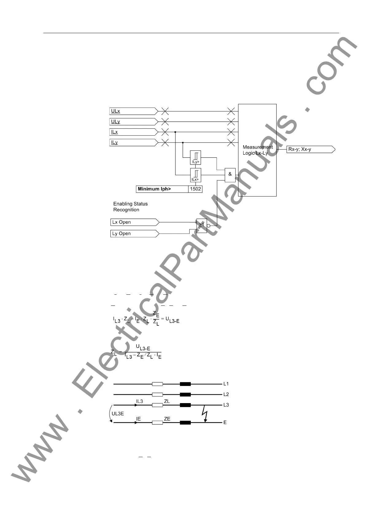
The calculation of the phase-phase loop does not take place as long as one of the con-
cerned phases is switched off (during single-pole dead time), to avoid an incorrect
measurement with the undefined measured values existing during this state. A state
recognition (refer to Section 2.23.1) provides the corresponding block signal. A logic
block diagram of the phase-phase measuring system is shown in Figure 2-34.
Figure 2-34 Logic for a phase–phase measuring unit
Phase–Earth Loops For the calculation of the phase-earth loop, for example during a L3-E (Figure 2-35) it
must be noted that the impedance of the earth return path does not correspond to the
impedance of the phase. In the loop equation
I
L3
· Z
L
– I
E
· Z
E
= U
L3-E
Z
E
is replaced by (Z
E
/Z
L
) · Z
L
yielding:
From this the line impedance can be extracted
Figure 2-35 Short-circuit of a phase-earth loop
The factor Z
E
/Z
L
solely depends on the line parameters and not on the fault distance.
www . ElectricalPartManuals . com
 Loading...


