2 Functions
120
7SD5 Manual
C53000-G1176-C169-1
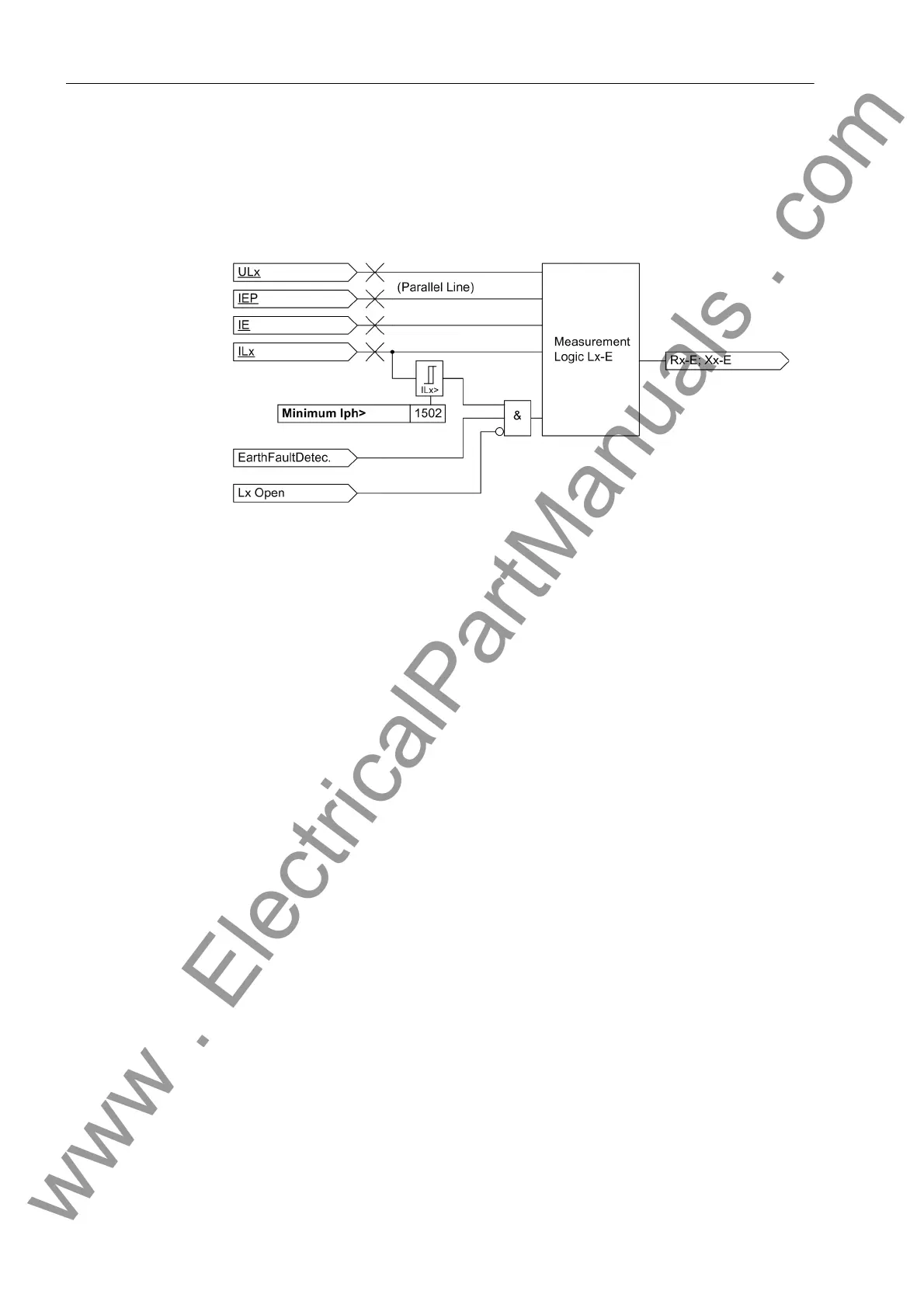
The evaluation of the phase-earth loop does not take place as long as the affected
phase is switched off (during single-pole dead time), to avoid an incorrect measure-
ment with the undefined measured values existing in this state. A state recognition
provides the corresponding block signal. A logic block diagram of the phase-earth
measuring system is shown in Figure 2-36.
Figure 2-36 Logic for a phase–earth measuring unit
Unfaulted Loops The above considerations apply to the relevant short-circuited loop. A pickup with the
current-based fault detection modes (I>, U/I, U/I/ϕ) guarantees that only the faulty
loop(s) are released for the distance calculation. All six loops are calculated for the im-
pedance pickup; the impedances of the unfaulted loops are also influenced by the
short-circuit currents and voltages in the short-circuited phases. During a L1-E fault for
example, the short-circuit current in phase L1 also appears in the measuring loops L1-
L2 and L3. The earth current is also measured in loops L2-E and L3-E. Combined with
load currents which may flow, the unfaulted loops produce the so called „apparent im-
pedances“ which have nothing to do with the actual fault distance.
These „apparent impedances“ in the unfaulted loops are usually larger than the short-
circuit impedance of the faulted loop because the unfaulted loop only carries a part of
the fault current and always has a larger voltage than the faulted loop. For the selec-
tivity of the zones, they are usually of no consequence.
Apart from the zone selectivity, the phase selectivity is also important to achieve
correct identification of the faulted phases, required to alarm the faulted phase and es-
pecially to enable single-pole automatic reclosure. Depending on the infeed condi-
tions, close-in short-circuits may cause unfaulted loops to „see“ the fault further away
than the faulted loop, but still within the tripping zone. This would cause three-pole trip-
ping and therefore void the possibility of single-pole automatic reclosure. As a result
power transfer via the line would be lost.
In the 7SD5 this is avoided by the implementation of a „loop verification“ function which
operates in two steps:
Initially, the calculated loop impedances and its components (phase and/or earth) are
used to simulate a replica of the line impedance. If this simulation returns a plausible
line image, the corresponding loop pickup is designated as a definitely valid loop.
If the impedances of more than one loop are now located within the range of the zone,
the smallest is still declared to be a valid loop. Furthermore, all loops that have an im-
pedance which does not exceed the smallest loop impedance by more than 50% are
declared as being valid. Loops with larger impedance are eliminated. Those loops
www . ElectricalPartManuals . com
 Loading...


