2.5 Distance Protection
139
7SD5 Manual
C53000-G1176-C169-1
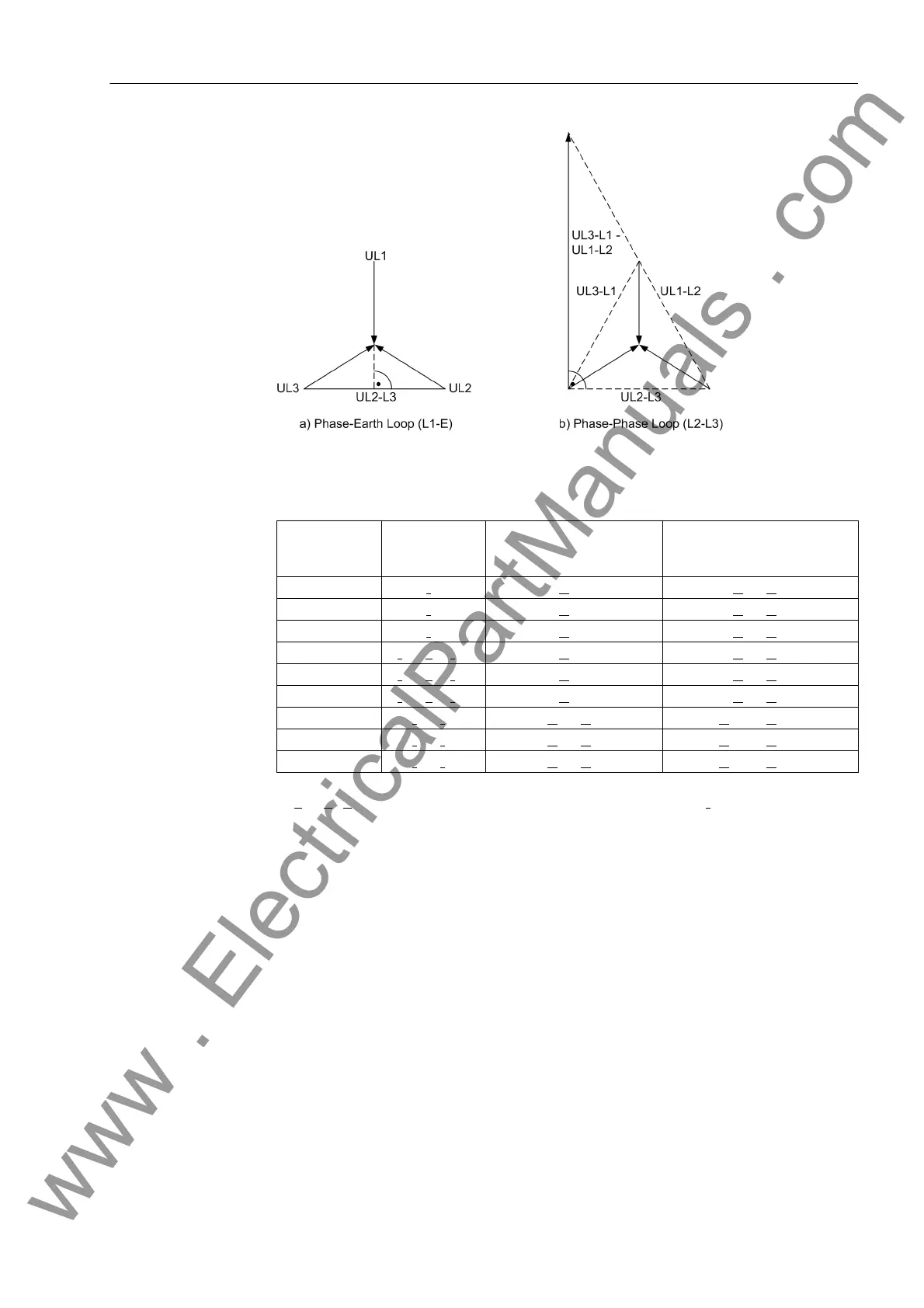
Figure 2-42 Direction determination with quadrature voltages
Table 2-11 Voltage and current values for the determination of fault direction
1)
k
E
= Z
E
/Z
L
; if only one phase-earth loop picks up, the earth current I
E
is taken into account.
If there is neither a current measured voltage nor a memorized voltage available which
is sufficient for measuring the direction, the relay selects the Forward direction. In
practice this can only occur when the circuit breaker closes onto a de-energized line,
and there is a fault on this line (e.g. closing onto an earthed line).
Figure 2-43 shows the theoretical steady-state characteristic. In practice, the position
of the directional characteristic when using memorized voltages is dependent on both
the source impedance as well as the load transferred across the line prior to fault in-
ception. Accordingly the directional characteristic includes a safety margin with
respect to the limits of the first quadrant in the R–X diagram (Figure 2-43).
Loop Measuring
Current (Direc-
tion)
Actual short-circuit
voltage
Quadrature voltage
L1-E I
L1
U
L1-E
U
L2
- U
L3
L2-E I
L2
U
L2-E
U
L3
- U
L1
L3-E I
L3
U
L3-E
U
L1
- U
L2
L1-E
1)
I
L1
- k
E
· I
E
1)
U
L1-E
U
L2
- U
L3
L2-E
1)
I
L2
- k
E
· I
E
1)
U
L2-E
U
L3
- U
L1
L3-E
1)
I
L3
- k
E
· I
E
1)
U
L3-E
U
L1
- U
L2
L1-L2 I
L1
- I
L2
U
L1
- U
L2
U
L2-L3
- U
L3-L1
L2-L3 I
L2
- I
L3
U
L2
- U
L3
U
L3-L1
- U
L1-L2
L3-L1 I
L3
- I
L1
U
L3
- U
L1
U
L1-L2
- U
L2-L3
www . ElectricalPartManuals . com
 Loading...


