2.6 Power Swing Detection (optional)
171
7SD5 Manual
C53000-G1176-C169-1
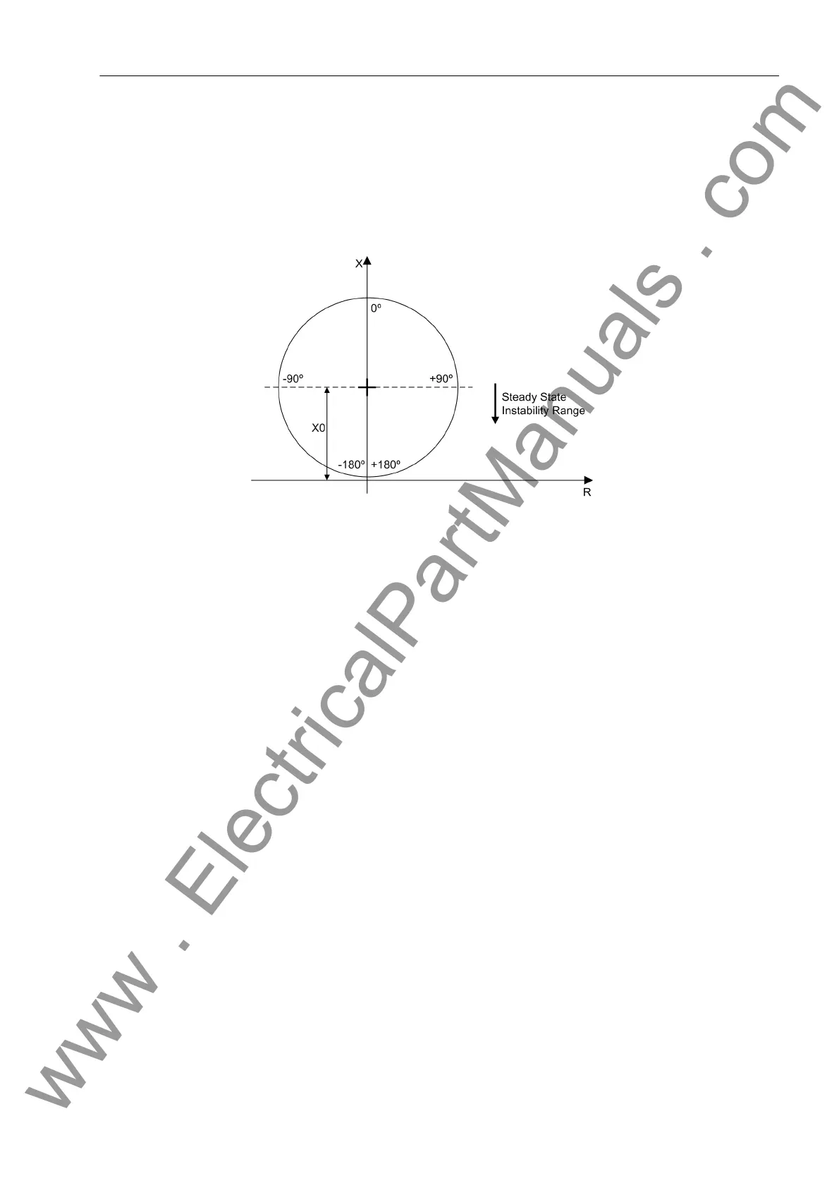
Trajectory Stability When the impedance vector enters the impedance characteristic during a power
swing this is on a point of the elliptical curve that corresponds to steady state instabil-
ity. For release of the power swing detection a further criterion is therefore used. In
Figure 2-64 the range for steady state instability is shown. This range is detected in
7SD5. This is done by calculating the centre of the ellipse and checking if the actual
measured X value is less than this value.
Figure 2-64 Steady state instability range
Trajectory
Symmetry
In addition to these measures, a comparison of the three phases is done to ensure that
they are symmetrical. During a power swing condition in the single pole open condi-
tion, only two of the three phases will have an impedance trajectory. In this case only
these 2 remaining phase trajectories are checked to ensure that they are symmetrical.
Power Swing
Detection
To ensure stable and secure operation of the power swing detection without risking un-
wanted power swing blocking during power system faults, a logical combination of a
number of measuring criteria are used.
www . ElectricalPartManuals . com
 Loading...


