2 Functions
172
7SD5 Manual
C53000-G1176-C169-1
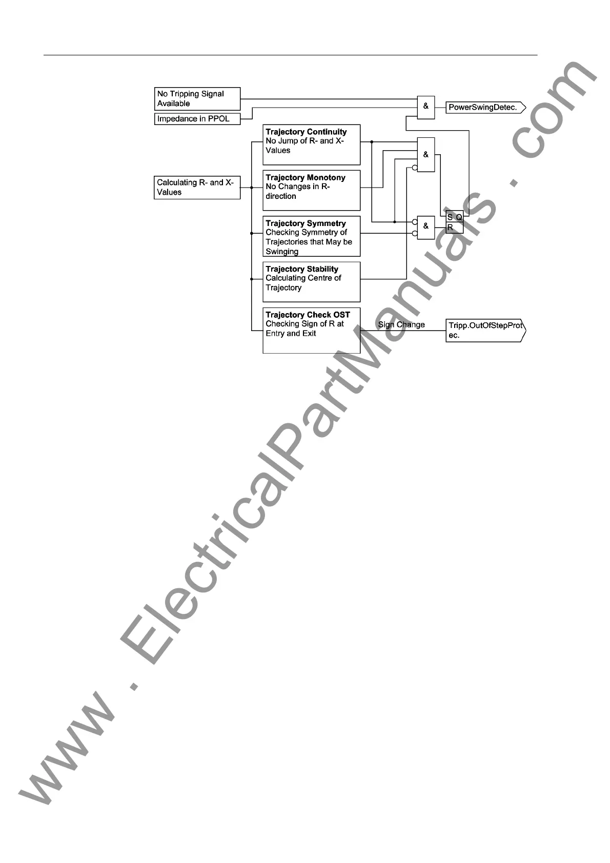
Figure 2-65 Logic diagram of power swing detection
In Figure 2-65 a simplified logic diagram for the power swing function is given. This
measurement is done on a per phase basis although Figure 2-65 only shows the logic
for one phase. Before a power swing detected signal is generated, the measured im-
pedance must be inside the power swing polygon (PPOL).
In the following there are 4 measuring criteria:
Trajectory continuity The calculated R and X values must create a constant
line. There must be no jump from one measured value
to the next. Refer to Figure 2-63.
Trajectory monotony The impedance trajectory must initially not change R-
direction. Refer to Figure 2-63.
Trajectory symmetry The trajectory of each phase is evaluated. If no fault is
present these 3 trajectories must be symmetrical.
During single pole open conditions the remaining 2 tra-
jectories must be symmetrical.
Trajectory stability When the impedance trajectory enters the PPOL
during a swing condition, the system must be in the
area of steady state instability. In Figure 2-64 this cor-
responds to the lower half of the circle.
All these conditions must be true for the generation of a power swing block condition.
Once the power swing block condition is set it will remain picked up until the imped-
ance vector leaves the power swing polygon (PPOL). This is unless a fault occurs
during this phase. The detection of a jump in the trajectory or non-symmetry of the tra-
jectories will reset the power swing blocking condition. The power swing detection can
be blocked via a binary input.
www . ElectricalPartManuals . com
 Loading...


