Configuration
84
7SS52 V4 Manual
C53000-G1176-C182-3
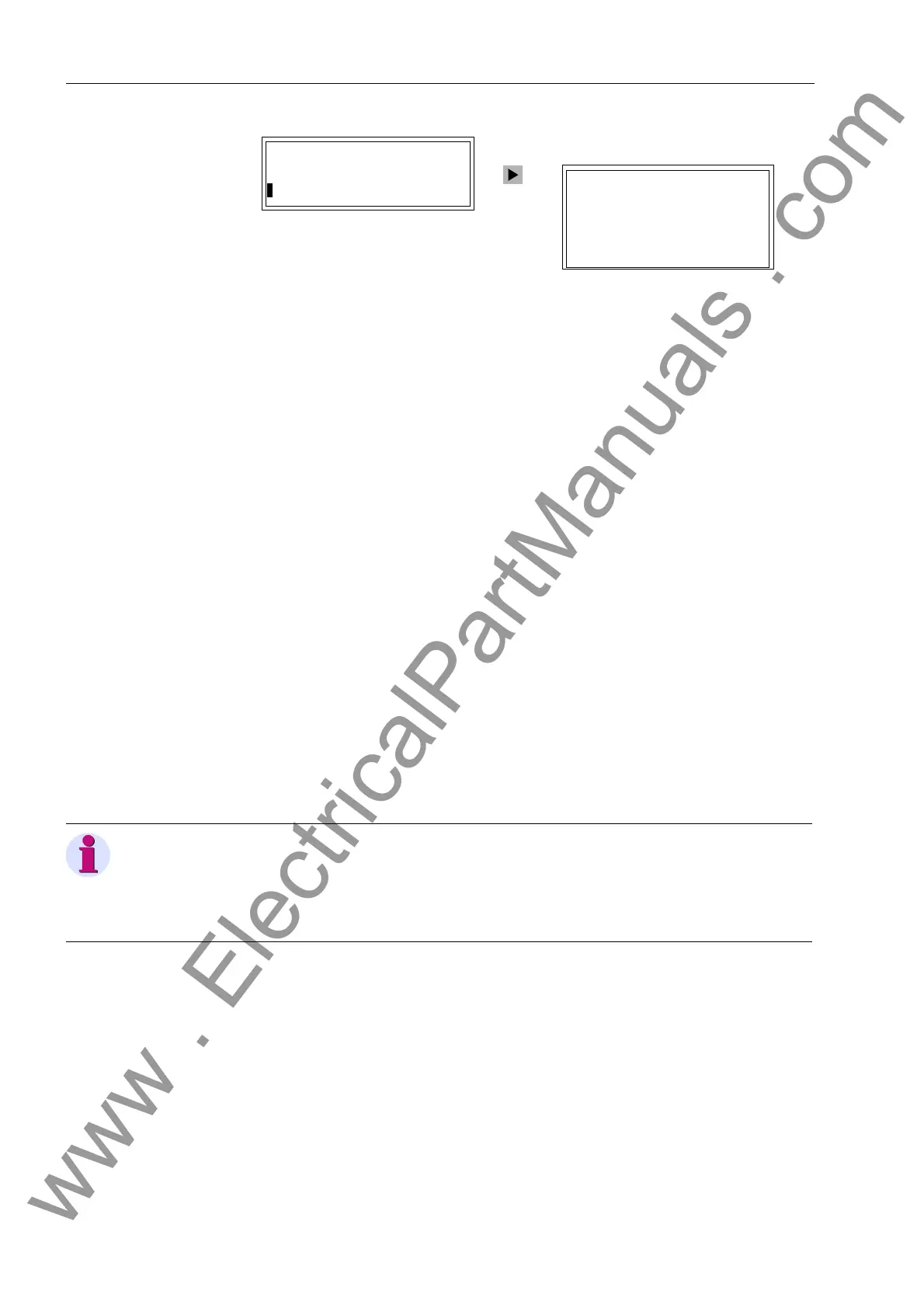
Figure 4-33 Reading out the setting values of the IEC 60870 port in the operator panel of the
device.
Bay units To enable correct communication of the PC and the bay units via the system port,
some interface settings may have to be verified or changed.
To verify or change the settings for the PC port and for the system port you must:
Right-click Configuration in the list view. Click Configure in the context menu. You
can also double-click Configuration. Both methods will open the dialog box Oper-
ating System Configuration.
In the column Function select the entry PC AND SYSTEM INTERFACES. Subse-
quently click Configure. A second dialog box opens It shows the names of all pa-
rameters together with an address and the currently set value.
Select a parameter to change its value and then click Configure. A third dialog box
opens It offers you possible values for the selected parameter.
Select the desired value. Subsequently click OK. The current dialog box closes and
you return to the previous dialog box. The display in the column Value is updated
according to your selection.
Repeat the procedure for further parameters. Click Close to finish the procedure.
The current dialog box closes and you return to the dialog box Operating System
Configuration.
Click Close. Next you will be prompted whether to save the modified settings to
files. Click Yes to save the data. Click No to discard the changes. To neither save
nor discard the modified settings click Cancel. In this case the dialog box Operat-
ing System Configuration remains opened.
PC Port 01/02
--------------------
>IEC60870–5–103 –> 1
IEC 60870–5–103
--------------------
>Phys.Address 254
>Baudrate 9600 bauds
Parity 8E1
Gaps 0.0s
OFF-Sig. Light OFF
Note
If you change the device address of a bay unit, you must reassign the bay unit in the
DIGSI Device Manager (see Chapter 4.5, page 71) to enable the configured substa-
tion chart to be opened in the Plant Visualization and there to display the latest chang-
es of the measured values and switch states.
www . ElectricalPartManuals . com
 Loading...


