Design and Connection System
18
7SS52 V4 Manual
C53000-G1176-C182-3
2.2 Bay Unit
The bay units are available in a 7XP20 housing for panel flush mounting and cubicle
mounting, or in a housing for panel surface mounting for bay unit 7SS523.
2.2.1 Front View
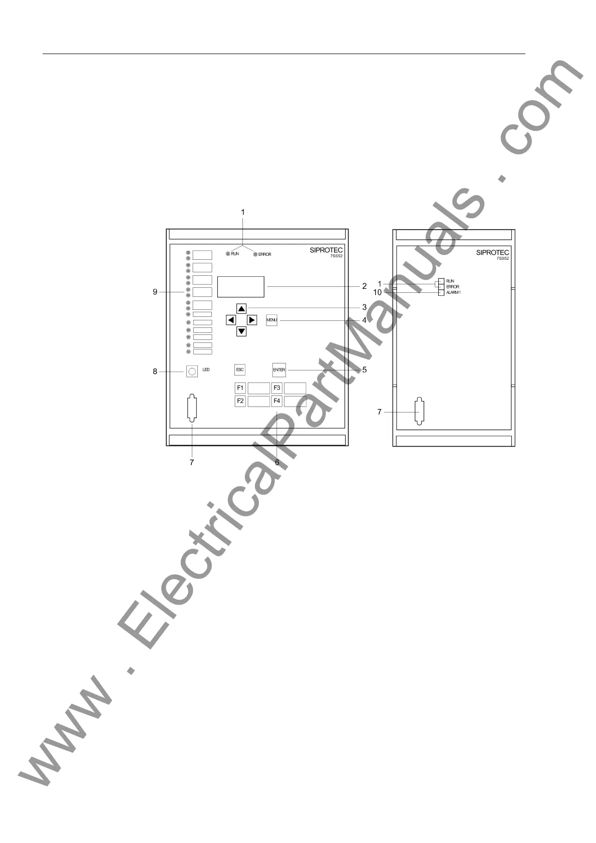
Figure 2-3 Front view of the bay unit 7SS523 and 7SS525
1 LEDs for the indication of operating states
2 LCD for textual display of process and device information
3 Navigation keys for moving through the operating tree
4 MENU key: no function
5 ENTER key:
for confirmation of inputs,
for entering the next level, or
for switching between ordering code (MLFB) and operational measured values
ESC key to move up one level
6 Function keys:
F1 Direct access to the operating tree for changing the mode
F2 Starts the circuit breaker test
F3: Direct access to the operating tree for switching the revision function
F4: Transformer polarity reversal
7 9-pole female sub D connector for connecting a PC running DIGSI
www . ElectricalPartManuals . com
 Loading...


