Design and Connection System
16
7SS52 V4 Manual
C53000-G1176-C182-3
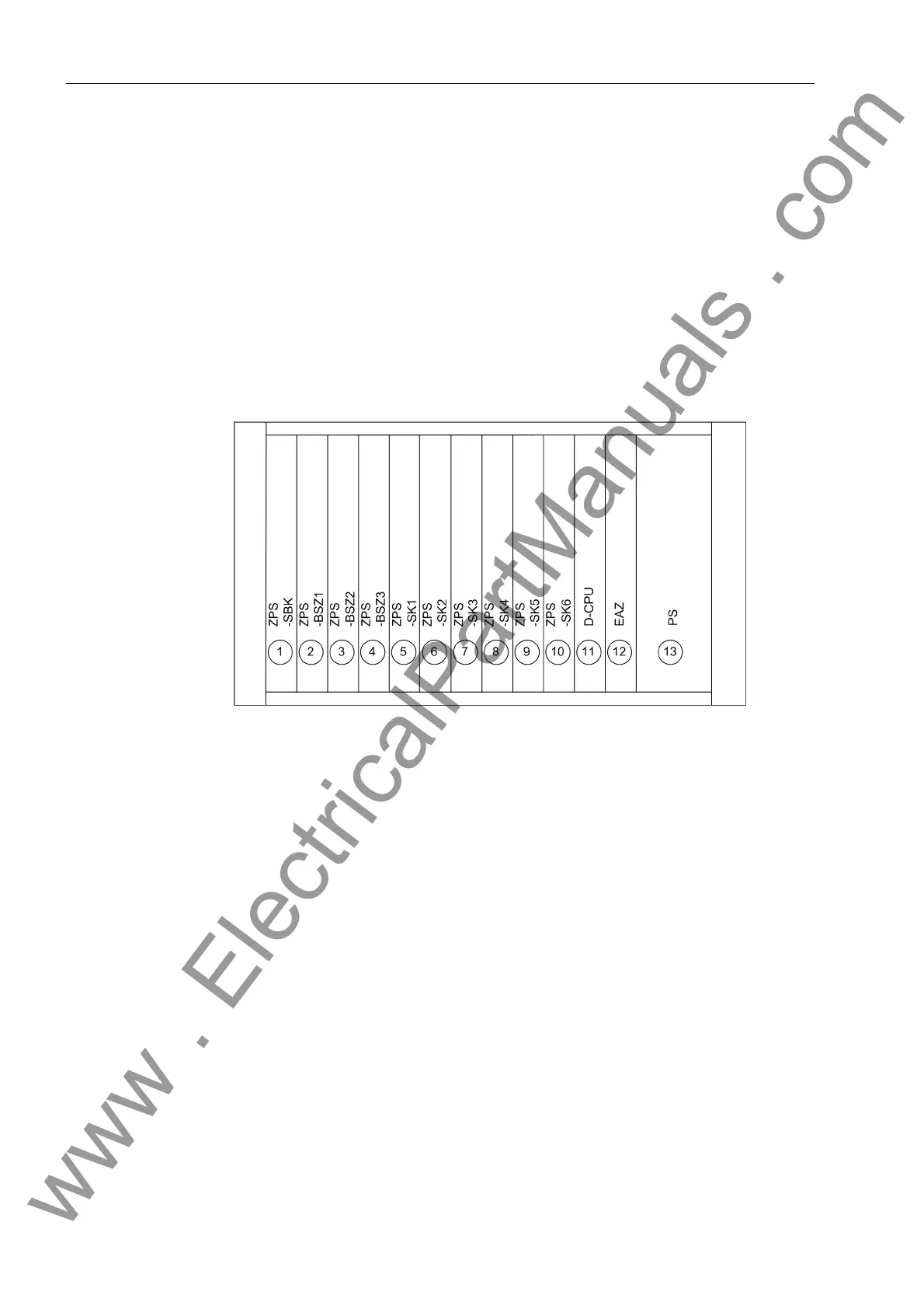
2.1.2 Modules and Submodules
Figure 2-2 Module arrangement in the central unit
Power supply mod-
ule (SV)
The power supply (SV) has a width of 4 standard mounting spaces.
Each of the other units has a width of 2 standard mounting spaces.
Communication
module (D-CPU)
The communication module (D-CPU) is used for communication between the central
unit and the DIGSI software. It also offers a control center interface, a service port and
5 binary inputs. An integrated electrical EN100 module for the communication via
IEC 61850 is optionally available.
Input/output
module (EAZ)
The I/O module (EAZ) comprises 16 alarm relays.
8 Function keys:
F1
Alarm list
F2 Operational events
F3 Measured values
F4 Last fault
9 freely parameterizable LEDs for display of process or device information. Next
to the LEDs, there is a labeling strip for labeling of the function of each LED.
10 LED key for testing and resetting the LEDs
www . ElectricalPartManuals . com
 Loading...


