Settings
−
Central Unit
355
7SS52 V4 Manual
C53000-G1176-C182-3
1) Delivery setting
Note
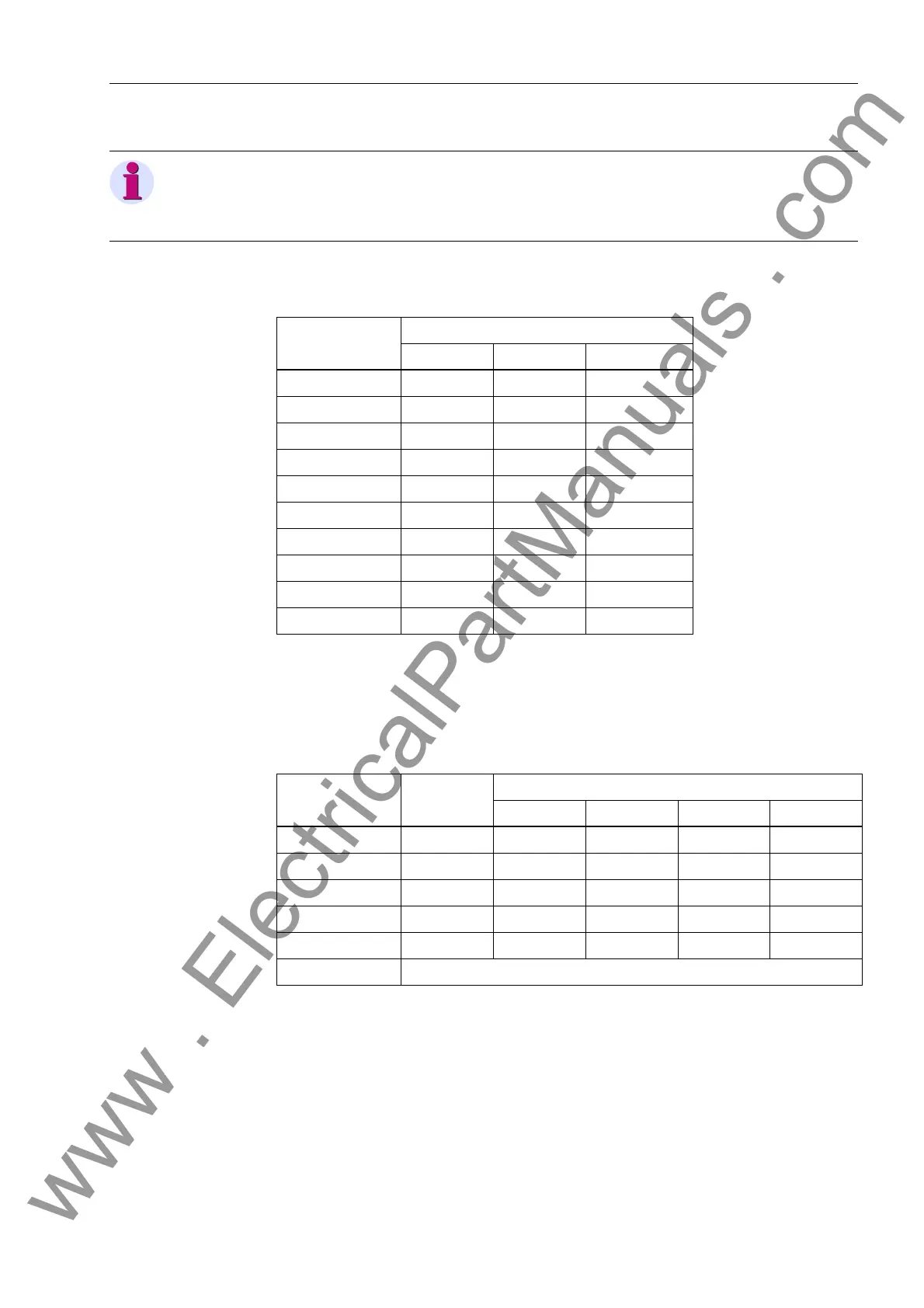
The jumpers settings on the connectors X103 and X104 must always be the same, i.e.
either both on 1-2 or both on 2-3.
Table A-14 Jumper settings (service port) for the D-CPU-module
Connector Jumper
RS232 RS485 optical
X103 1-2
1)
any
X104 1-2
1)
any
X105 1-2 2-3 any
X106 1-2 2-3 any
X107 1-2 2-3 any
X108 1-2 2-3 1-2
X109 1-2 2-3 any
X110 1-2 2-3 any
X111 2-3 2-3 2-3
X112 2-3 2-3 1-2
1) 2-3, switches the terminating resistors on if the device is connected to the beginning or
the end of a RS485 bus line.
1-2, switches he terminating resistors off
Table A-15 Jumper settings (binary inputs) for the D-CPU module
Connector Binary-
inputs
Jumper
24 V 60 V 110 V 220V
1)
X20, X21 BI1 1-1 2-2 3-3 4-4
X22, X23 BI2 1-1 2-2 3-3 4-4
X24, X25 BI3 1-1 2-2 3-3 4-4
X26, X27 BI4 1-1 2-2 3-3 4-4
X28, X29 BI5 1-1 2-2 3-3 4-4
BI6 to BI12 (on module EAZ, Table A-12, page 353)
www . ElectricalPartManuals . com
 Loading...


