Preface
vi
7SS52 V4 Manual
C53000-G1176-C182-3
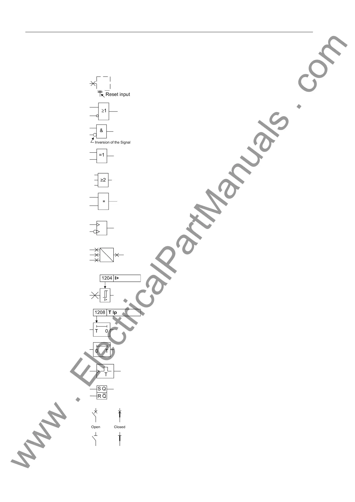
Besides these, graphical symbols are used according to IEC 60 617–12 and
IEC 60 617–13 or symbols derived from these standards. The most frequent symbols
are the following:
Input signal of an analogue quantity
OR-combination of input values
AND-combination of input values
Exclusive–OR gate: output is active, if only one of the
inputs is active
2-of-3-combination of input values
Coincidence: output is active if both inputs are active
or inactive at the same time
Dynamic input signals (edge–triggered) above with
positive, below with negative edge
Formation of one analogue output signal from a
number of analogue input signals
Limit value stage with parameter address and param-
eter name
Timer (pickup delay T adjustable) with parameter
address and parameter name
Timer (dropout delay T, non-adjustable)
Edge-controlled time stage with effective time T
Static memory (RS-flipflop) with setting input (S),
resetting input (R), output (Q) and inverted output (Q)
Circuit breaker (open and closed)
Isolator (open and closed)
www . ElectricalPartManuals . com
 Loading...


