Functions
2.16 Backup Time Overcurrent Protection
SIPROTEC, 7SD5, Manual
C53000-G1176-C169-5, Release date 02.2011
305
or T 3I0p Add may be selected, which is added to the inverse time. The possible characteristics are shown
in the Technical Data.
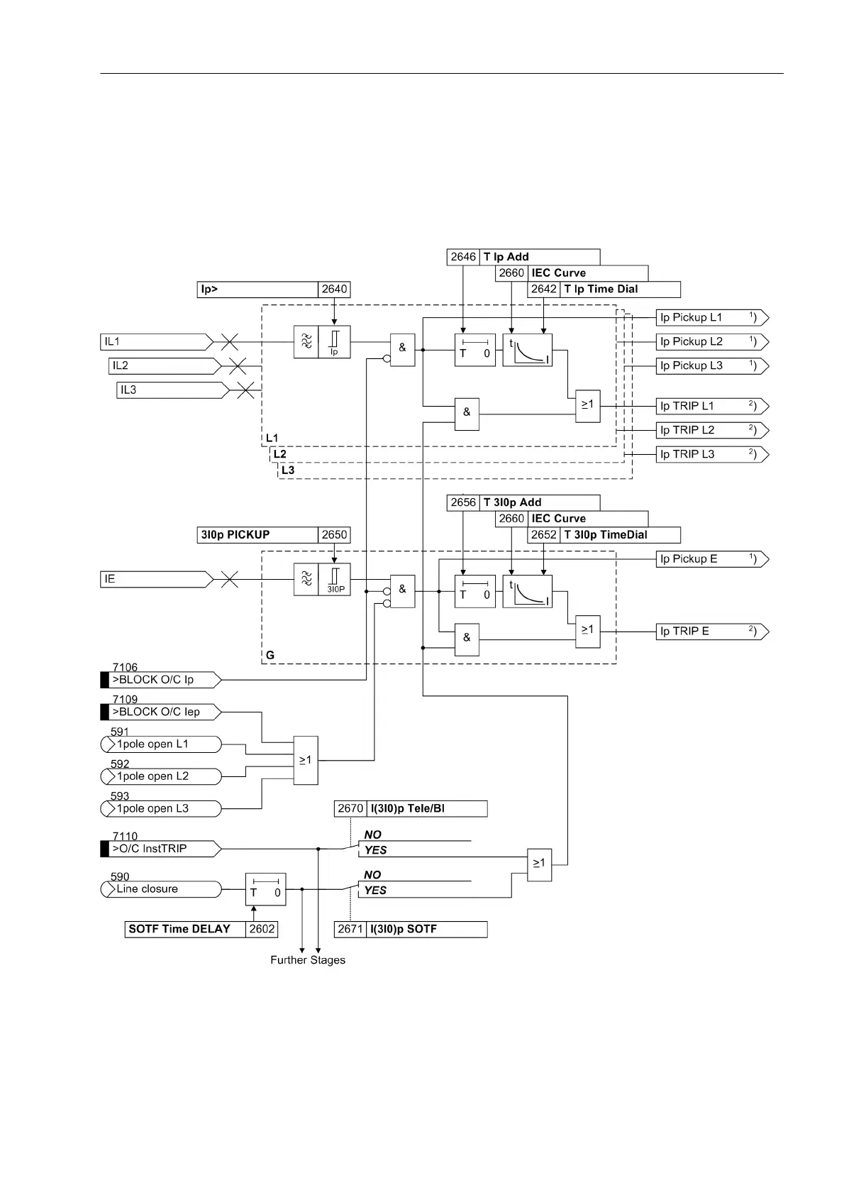
The following figure shows the logic diagram. The setting parameter addresses of the IEC characteristics are
shown by way of an example. In the setting information (Section 2.16.3) the different setting addresses are
elaborated upon.
Figure 2-154 Logic diagram of the I
P
stage (inverse time overcurrent protection) - example of IEC curve
1
) Output indications associated with the pickup signals are listed in Table 2-12
2
) Output indications associated with the trip signals are listed in Table 2-13

 Loading...


