Functions
2.16 Backup Time Overcurrent Protection
SIPROTEC, 7SD5, Manual
C53000-G1176-C169-5, Release date 02.2011
304
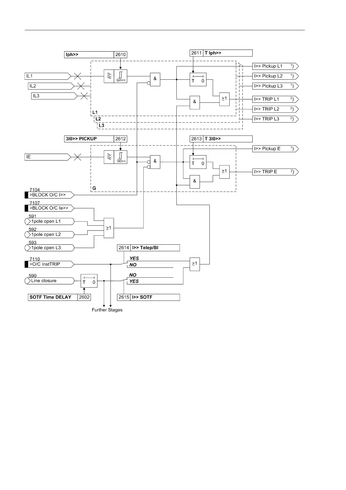
Figure 2-153 Logic diagram of the I>> stage
1
) Output indications associated with the pickup signals are listed in Table 2-12
2
) Output indications associated with the trip signals are listed in Table 2-13
Definite time overcurrent stage I>
The logic of the overcurrent stages I> is structured identically to the I>> stages. In all references, Iph>> must
merely be replaced by Iph> or 3I0>> PICKUP by 3I0>. The parameter 2624 I> Telep/BI is set to NO by
default. In all other respects, figure 2-153 applies.
Inverse time overcurrent stage I
P
The logic of the inverse overcurrent stage also operates chiefly in the same way as the remaining stages. How-
ever, the time delay is calculated here based on the type of the set characteristic, the intensity of the current
and a time multiplier (following figure). A pre-selection of the available characteristics was already carried out
during the configuration of the protection functions. Furthermore, an additional constant time delay T Ip Add

 Loading...


