Mounting and Commissioning
3.1 Mounting and Connections
SIPROTEC, 7SD5, Manual
C53000-G1176-C169-5, Release date 02.2011
504
The allocation of the boards for housing size
1
/
2
is shown in Figure 3-3 and for housing size
1
/
1
in Figure 3-4.
• Disconnect the plug connector of the ribbon cable between the front cover and the processor board C-CPU-
1 (No. 1) at the front cover side. For this purpose push apart the top and bottom latches at the plug connector
so that the ribbon cable connector is pressed out.
• Disconnect the plug connector of the ribbon cable between processor board C-CPU-1 (No. 1 in Figure 3-3
or 3-4) and the I/O input/output modules (depending on order variant No. 2 to No. 3 in Figure 3-3 or No. 2
to 4 in Figure 3-4).
• Remove the boards and place them on a surface suitable for electrostatically sensitive devices (ESD). In
devices designed for panel surface mounting, a certain amount of force is required to remove the C-CPU-1
module due to the existing plug connectors.
• Check the jumpers according to Figures 3-5 to 3-13 and the following information. Change or remove the
jumpers if necessary.
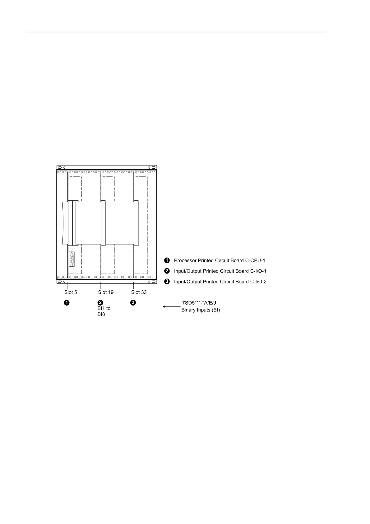
Figure 3-3 Front view with housing size
1
/
2
after removal of the front cover (simplified and scaled down)

 Loading...


