Typical circuit diagrams
16.9 EMERGENCY STOP
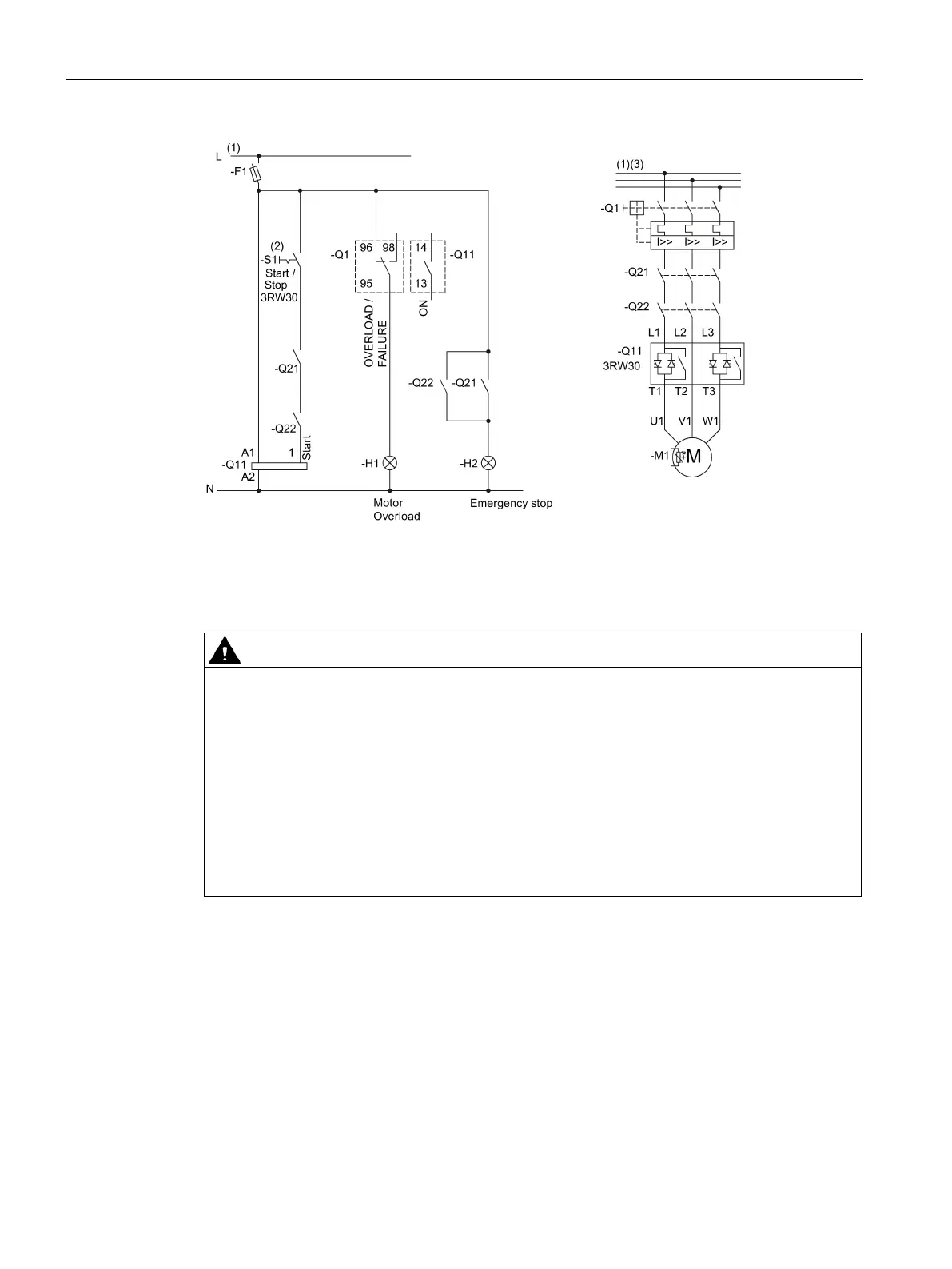
SIRIUS 3RW30 / 3RW40
184 Manual, 10/2018, NEB535199502000/RS-AB/005
Figure 16-24 Wiring of the 3RW30 control and main circuits
(1) For permissible main and control voltage values (dependent on article number), refer to
chapter Technical data (Page 127).
(2) Automatic restart. Can result in death, serious injury, or property damage.
- If the 3TK28 is reset
- Faults caused by incorrect control voltage, a missing load, or a phase failure (refer to
chapter 3RW30: LEDs (Page 57)) are automatically reset when the system returns to
normal.
An automatic restart is initiated and the 3RW restarted if a start command is present at the
input.
If you do not want the motor to start automatically, you must integrate suitable additional
components, e.g. phase failure or load monitoring devices, into the control and main
circuits.
(3) Alternatively, the motor feeder can be assembled as a fuseless or fused version with type
of coordination 1 or 2. For the assignment of fuses and switching devices, refer to chapter
Technical data (Page 127).
 Loading...


