EasyManuals Logo

Siemens SIRIUS User Manual

Siemens SIRIUS
168 pages
To Next Page IconTo Next Page
To Previous Page IconTo Previous Page
Page #52 background imageLoading...
Page #52 background image
Mounting
7.2 Mounting and disassembling load feeders
SIRIUS - SIRIUS 3RA load feeders
52 Manual, 09/2016, A5E03656507520A/RS-AB/003
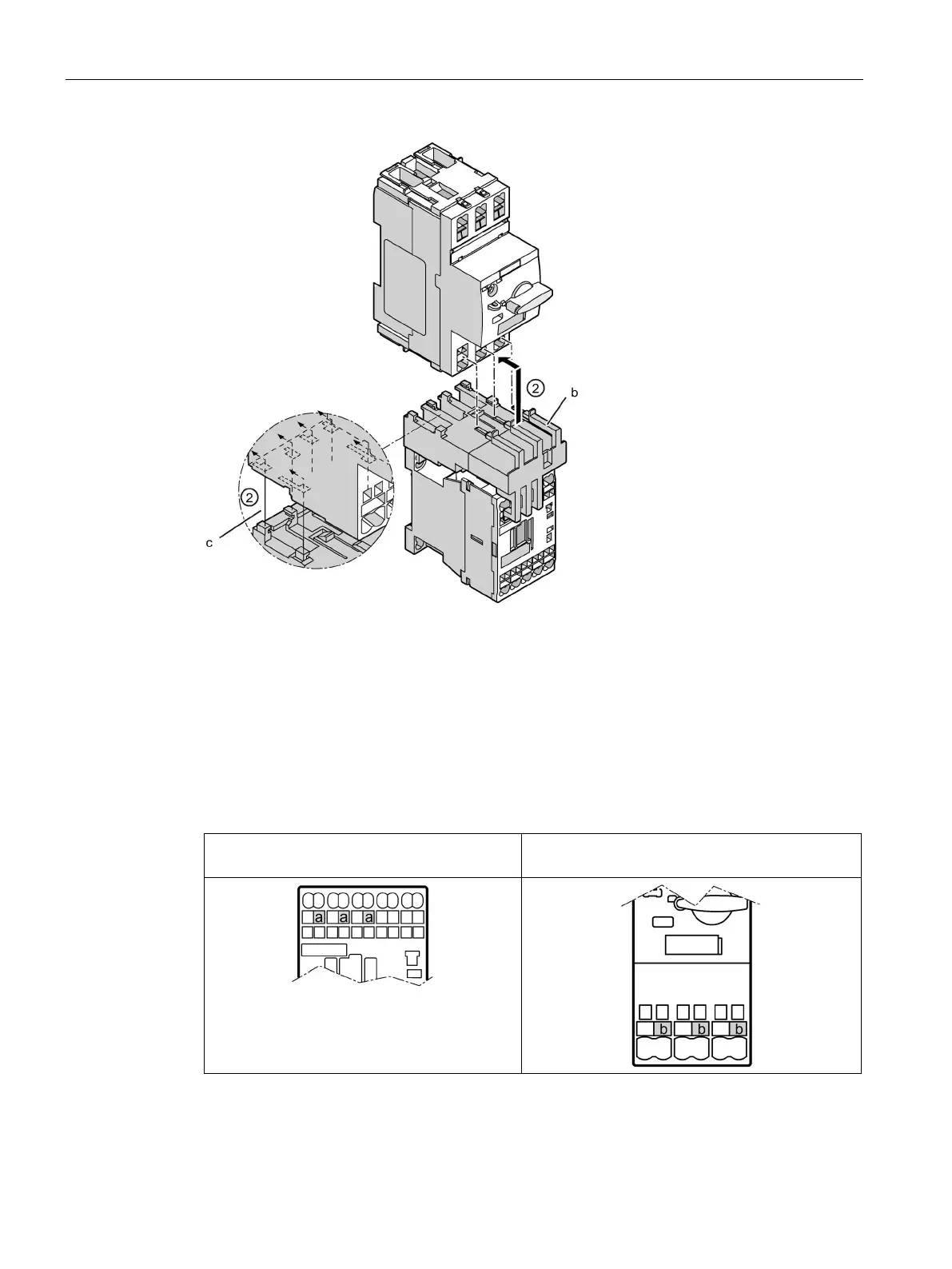
Insert the connectors on the link module (b) into the corresponding main conductor terminals
on the motor starter protector.
Insert the guide tabs (c) into the designated slots at the same time.
The link module will sit flush underneath the motor starter protector on the left- and right-hand
sides.
Figure 7-5 Mounting an S00 load feeder with spring-loaded connection system
Table 7- 5 Main conductor terminals on contactor and motor starter protector (size S00)
Main conductor terminals on the contactor (a)
(S00):
Main conductor terminals on the motor starter
protector (b) (S00):

Table of Contents

Other manuals for Siemens SIRIUS

Questions and Answers:

Question and Answer IconNeed help?

Do you have a question about the Siemens SIRIUS and is the answer not in the manual?

Siemens SIRIUS Specifications

General IconGeneral
Product brand nameSiemens
SeriesSIRIUS
Coil Voltage24V DC, 110V AC, 230V AC
Switching CapacityUp to 10A
Mounting TypeDIN rail
Product designationSIRIUS
Contact MaterialSilver alloy
Contact RatingVaries depending on the specific SIRIUS relay model (e.g., 6 A at 250 V AC, 10 A at 250 V AC)
Switching VoltageVaries depending on the specific SIRIUS relay model (e.g., 250 V AC, 400 V AC)
Mechanical LifeUp to 10 million operations
Electrical LifeUp to 100, 000 operations
Operating Temperature-25°C to +55°C
Protection ClassIP20
Size of relay baseVaries depending on the specific SIRIUS relay model

Related product manuals