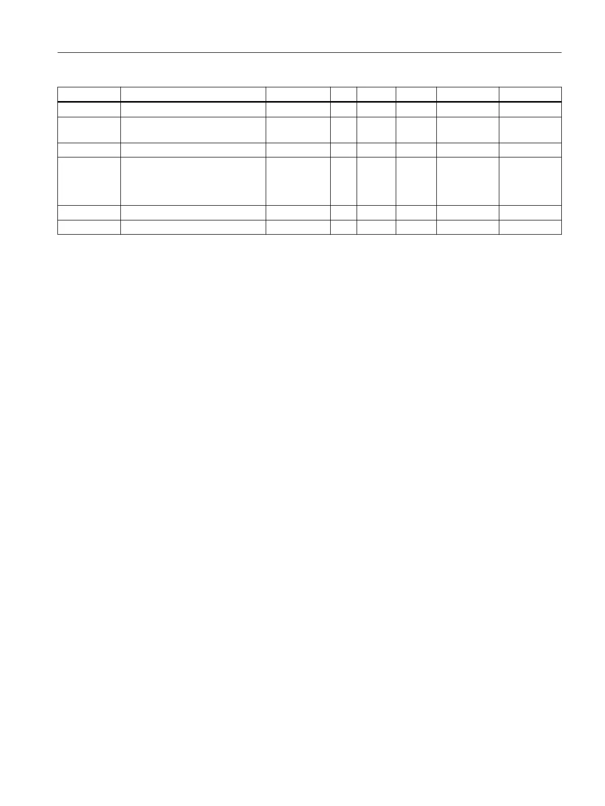
Variable Note Type L Rw Default Min. Max.
Bit 2 BIT 0 rw 0 0 1
Reserve (13
bits)
Reserve BIT 0 rw 0 0 1
Reserve Reserve UINT 2 rw 20 1 255
Decimal
place for Sie‐
bert indicator
(Page 81)
Decimal place for Siebert display INT 2 rw 0 - -
Reserve Reserve UINT 2 rw 0 - -
Reserve Reserve REAL 4 rw 0 - -
8.11.1 RS485 protocol
This parameter defines the protocol for communication via the RS485 interface.
8.11.2 RS485 baud rate
This parameter defines the baud rate for the RS485 interface.
8.11.3 RS485 character parity
This parameter defines the character parity for the RS485 interface.
8.11.4 Decimal place for Siebert indicator
A fixed decimal place must be specified if a Siebert indicator is used. The following values are
permitted: 0 ... 4
8.12 DR 14 SIMATIC interface parameters
The parameters which define the response of the SIMATIC interface are specified in data
record DR 14. It is possible to define the process values to be output on the basis of the I/O area.
Procedure
● Check the parameters and modify them as required
● Transfer the data record to the scale
Scale parameters and functions
8.12 DR 14 SIMATIC interface parameters
SIWAREX WP321
Operating Instructions, 08/2019, A5E33715669A-AD 81