Do you have a question about the SIGLENT SSA3000X Series and is the answer not in the manual?
Details on product compliance with national and international standards.
Importance of proper grounding to prevent electric shock.
Precautions to prevent damage from electrostatic discharge.
Importance of adequate ventilation to prevent overheating and damage.
Explanation of terms like DANGER, WARNING, CAUTION used in the manual.
Identification and meaning of safety symbols like Hazardous Voltage, Ground, etc.
List of key features and benefits of the spectrum analyzer.
Methods for setting various instrument parameters.
Detailed explanation of the function keys and their areas on the front panel.
Description of the USB Host port for connecting external storage devices.
Description of the earphone jack for audio output of demodulated signals.
Interface for connecting to a PC for remote control via USB.
Interface for connecting to a local network for remote control.
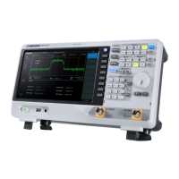
Labeled diagram of the spectrum analyzer's user interface.
How to check system information like model, serial, and software versions.
How to input parameters using numeric keys and Enter.
Setting parameters using the rotary knob.
How to access and use the instrument's built-in help system.
Covers fundamental settings like frequency, span, and amplitude.
Options for performing various measurement tasks.
Setting the center, start, and stop frequencies of the analyzer.
How to set the center frequency and its related parameters.
How to set the span and its effects on start/stop frequencies.
Setting the reference level for amplitude measurements.
Adjusting the input attenuator for signal handling.
Setting the Y-axis units for amplitude display.
Compensating for gain/loss from external devices using correction factors.
Setting Resolution Bandwidth (RBW) and Video Bandwidth (VBW).
Setting trace types like Clear Write, Max Hold, Min Hold, etc.
Setting the duration for a single sweep.
Triggering signals continuously without conditions.
Enabling or disabling the first limit line.
Setting the output power level of the tracking generator.
Enabling AM or FM demodulation and performing it.
Basic marker operations and display.
Using a normal marker to measure X and Y values of a point.
Setting the center frequency to the current marker's frequency.
Measuring noise power spectral density at a marked point.
Executing peak search and setting CF to the peak frequency.
Measuring power within a specified channel bandwidth.
Measuring Adjacent Channel Power Ratio.
Setting parameters for Channel Power measurement.
Setting the bandwidth for the main channel in ACPR.
Setting parameters for Time-Power measurement.
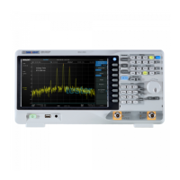
Setting parameters for Spectrum Monitor display.
Setting system parameters.
Selecting the display language for menus and help.
Configuring LAN parameters like IP address and DHCP.
Enabling automatic calibration process.
Testing the functionality of front panel keys.
Saving files to the current directory or external disk.
Steps to connect the analyzer to a PC via USB for remote control.
Connecting the analyzer via USB Host port, typically for GPIB adapters.
Steps to build communication using the NI-VISA software.
Controlling the analyzer using SCPI commands.
Sending SCPI commands via USB using NI-MAX.
Warranty information and terms for SIGLENT products.
Steps to diagnose and resolve common instrument problems.
Troubleshooting steps for inaccurate measurement results.
| Frequency Resolution | 1 Hz |
|---|---|
| Sweep Time | 1 ms to 1000 s |
| Displayed Average Noise Level (DANL) | -161 dBm/Hz (Typical) |
| Phase Noise | -98 dBc/Hz @ 10 kHz offset (1 GHz) |
| Display | 10.1 inch LCD (1024x600) |
| Input Impedance | 50 Ohm (Typical) |
| Interfaces | USB, LAN |
| Preamplifier | Optional |
| Tracking Generator | Optional |
| Power Requirements | 100 V - 240 V AC, 50 Hz / 60 Hz |