Electrical installation
25 / 196
4 Electrical installation
DANGER
Danger due to improper connection of the operating voltage.
Improper connection of the electrical service voltage can be life-threatening. The system can also
be damaged in the process.
u Connection must be carried out by a specialist in accordance with local regulations.
u Install a disconnecting device near the power supply to disconnect the device from the mains.
The disconnecting device should be easily accessible and labelled.
u Use shielded cables and connect the cable shield to earth.
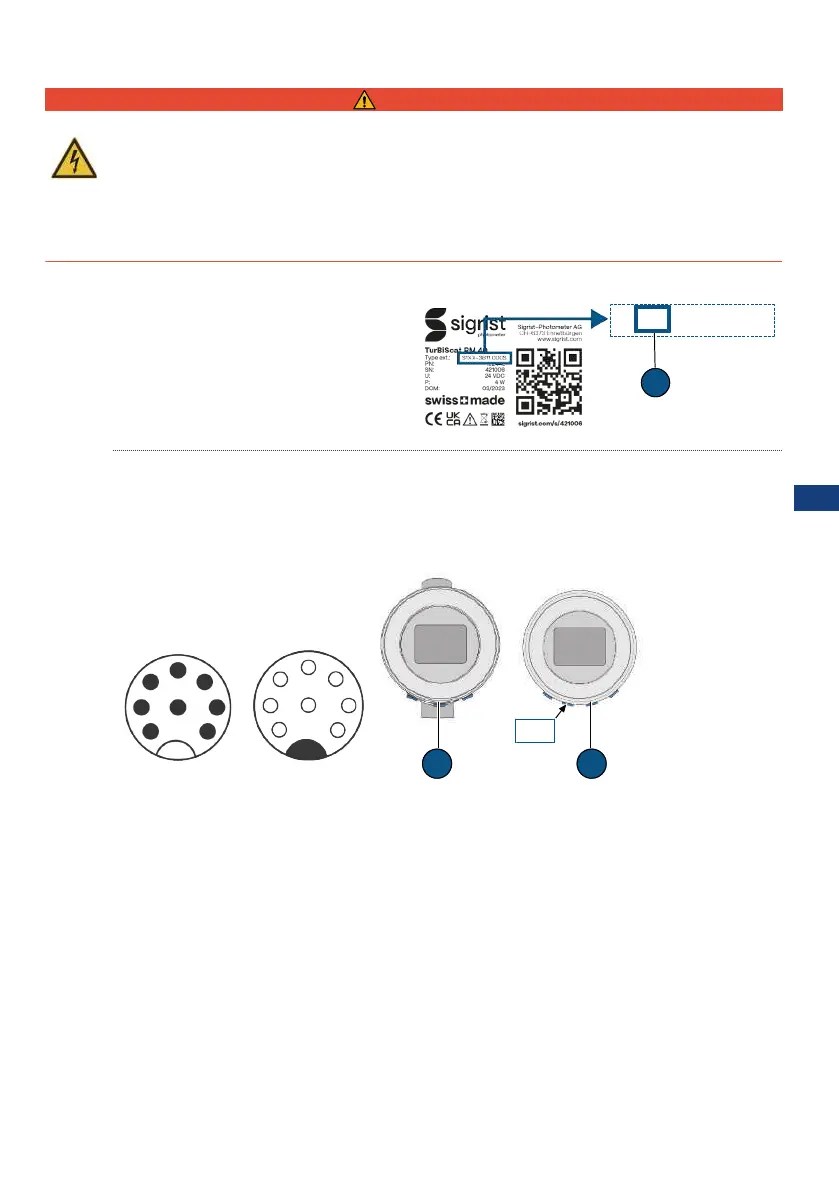
4.1 Determine communication module
The integrated communication module can
be seen on the type plate [}22]. The fol-
lowing codes (1) are possible: IO = EG_IO |
PE = EG_PoE | PB = EG_Profibus | PN =
EG_Profinet
4.2 Photometer connection
A distinction is made between two variants:
l Photometer (PM) with integrated display and connections
1)
l Photometer (PM) without display connected with SiDis AD 40
2)
4.2.1 EG_IO
1
2
8
3
4
5
6
7
Male (A)
A A
PM SiDis
PM
Female PM
3
7
2
1
8
4
6
5
1) 2)
Plug pin no. 1 2 3 4 5 6 7 8
(A) M12 8-pin plug A coded GND 24V IO6 IO4 IO2 IO3 IO1 IO5
RS485-Modbus RTU
(with/without 120 Ω termination)
B A
Digital input 5-28 VDC x x
Digital output "High Side Switch" max.
20mA
x x x x
Current output 0/4 ... 20 max. 700 Ω x x x x
DE
EN
FR
ES
NL
PT
ZH
RU
CS
JA
IT
PL
 Loading...