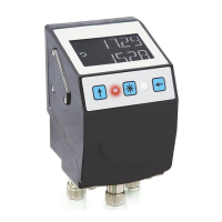
AP10S
Commissioning English
AP10S · Date 15.04.2020 · Art. No. 87100 · Mod. status 83/20
33
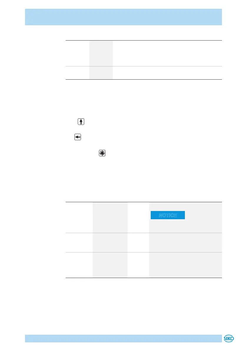
Color State Description
one LED
red
on Actual position value is outside the programmed
position window. The red LED indicates the direc-
tion of shaft rotation required to arrive at the set-
point.
both LED
red
o Actual position value is within the programmed
position window.
Configuration
The required parameters are set in the configuration mode. On the 1st line
of the display, the parameter will be shown and on the 2nd line the res-
pective value will be displayed.
Press key for changing actual value and / or the blinking digit when
entering a multi-digit value.
The key serves for switching to the next digit in case of multi-digit
numbers.
By pressing the key, the set value is acknowledged and saved non-
volatilely. If no key is pressed, the configuration mode will be exited after
~30s without saving the latest value displayed, i. e. the original value will
be maintained.
Configuration parameters CAN
Parameter Value range Default Meaning/Remark
ID 1 ... 127 125 bus address
NOTICE
Restart is required after chang-
ing these parameters!
KBAUD 125, 250, 500,
800, 1000kbd,
Auto
Auto CAN baud rate (e. g. 250kbit/s)
CODE 0 ... 999999
000100
011100
0 for test/diagnosis purposes
start alignment travel (see chap-
ter 5.2)
load factory settings
 Loading...