AP10S
Accessory connector English
AP10S · Date 15.04.2020 · Art. No. 87100 · Mod. status 83/20
39
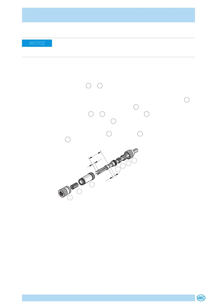
8.2 Straight matting connector M8
Advice
` Strand cross sections of lines 0.14 ... 0.25mm² / cable feed-through:
ø3.5 ... ø5mm.
• Accessory SIKO art. no. "84209" (female 4 pin Bus-IN/IO-Link).
• Accessory SIKO art. no. "84210" (pin 4 pin Bus-OUT).
Mounting (Fig. 10)
1. Slide parts
1
...
4
over cable sheath.
2. Strip the cable.
3. Shorten, expand the shielding and lay around the shielding ring
4
.
4. Run strands through coupling sleeve
5
and strip them.
5. Mount parts
2
...
4
. Turn pressure screw
1
to secure the cable.
6. Thread insulating sleeve
6
, solder strands and mount insulating
sleeve.
7. Screw coupling sleeve
5
with element
7
and tighten pressure screw
1
.
Fig. 10: Straight matting connector M8
8.3 Mating connector M8 bus terminator (RS485, CANopen)
For the fieldbus to function, a terminating resistor is required (120Ohm).
• Accessory SIKO art. no. "BAS-0005" (pin 4 pin).
For multiple position indicators on one bus: connect terminating plug to
bus OUT of the last bus station (see chapter 4.2).
For one position indicator: connect terminating plug to bus OUT (see chap-
ter 4.2).
NOTICE
 Loading...