AP10S
Installation English
AP10S · Date 15.04.2020 · Art. No. 87100 · Mod. status 83/20
30
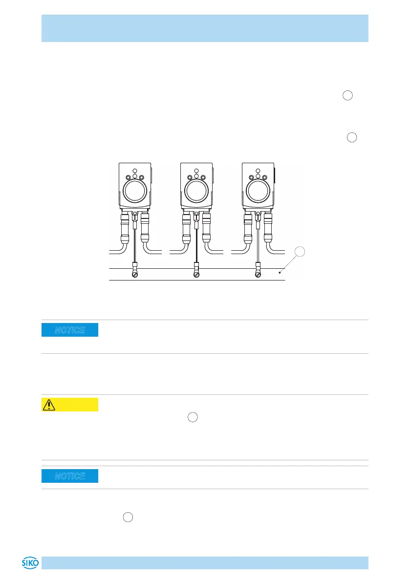
Ground connection
For protection against interference, the screens of the signal lines and the
power line must be connected on both sides. Potential dierences cause
inadmissible currents on the screen. Install the ground connection
4
onto the protective ground conductor potential between the plug con-
nectors (see Fig. 4). Use 6.3mm flat connectors or cable lug with short
strands 2.5 … 4mm² (not in the scope of delivery). For multiple position
indicators we recommend connecting the grounding to a ground bar
1
(see Fig. 5).
Fig. 5: Ground bar
Admissible power input
Supply for the position indicator shall be sized suciently. Current draw is
temporarily higher than nominal current at the moment of switching on.
For the supply value refer to the technical data in chapter 9.
4.4 Connection concept (IO-Link)
Position indicator failure
Removing the dust cap
4
and opening the screw results in loss of the pro-
tection type.
` Do not remove dust cap.
` Do not open the screw.
After connection of a new/other sensor, an adjustment speed is required
(see chapter 5.2).
Pin assignment
•
1
IO-Link: Pin 4 pin M8 (see Fig. 6).
For mating connector and cable extension accessories see chapter 8.
NOTICE
CAUTION
NOTICE
 Loading...