AP10S
Installation English
AP10S · Date 15.04.2020 · Art. No. 87100 · Mod. status 83/20
31
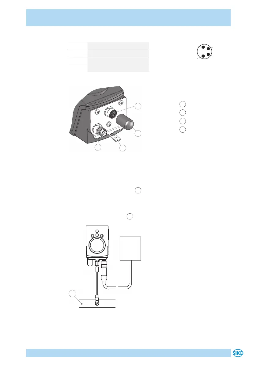
PIN Designation
1 L+ (+UB)
2 nc
3 L- (GND)
4 C/Q
1
Bus-IN
2
Sensor
3
Ground connection
4
Dust cap
1
2
3
4
Fig. 6: Pin assignment
Strand cross sections of lines 0.14 ... 0.5mm².
Ground connection
Install the ground connection
3
onto the protective earth conductor
potential between the plug connectors (see Fig. 6). Use 6.3mm flat con-
nectors or cable lug with short strands 2.5 … 4mm² (not in the scope of
delivery). For multiple position indicators we recommend connecting the
grounding to a ground bar
1
(see Fig. 7).
IO-Link
Master
1
Fig. 7: Ground bar
2
4
viewing side = plug-in side
 Loading...